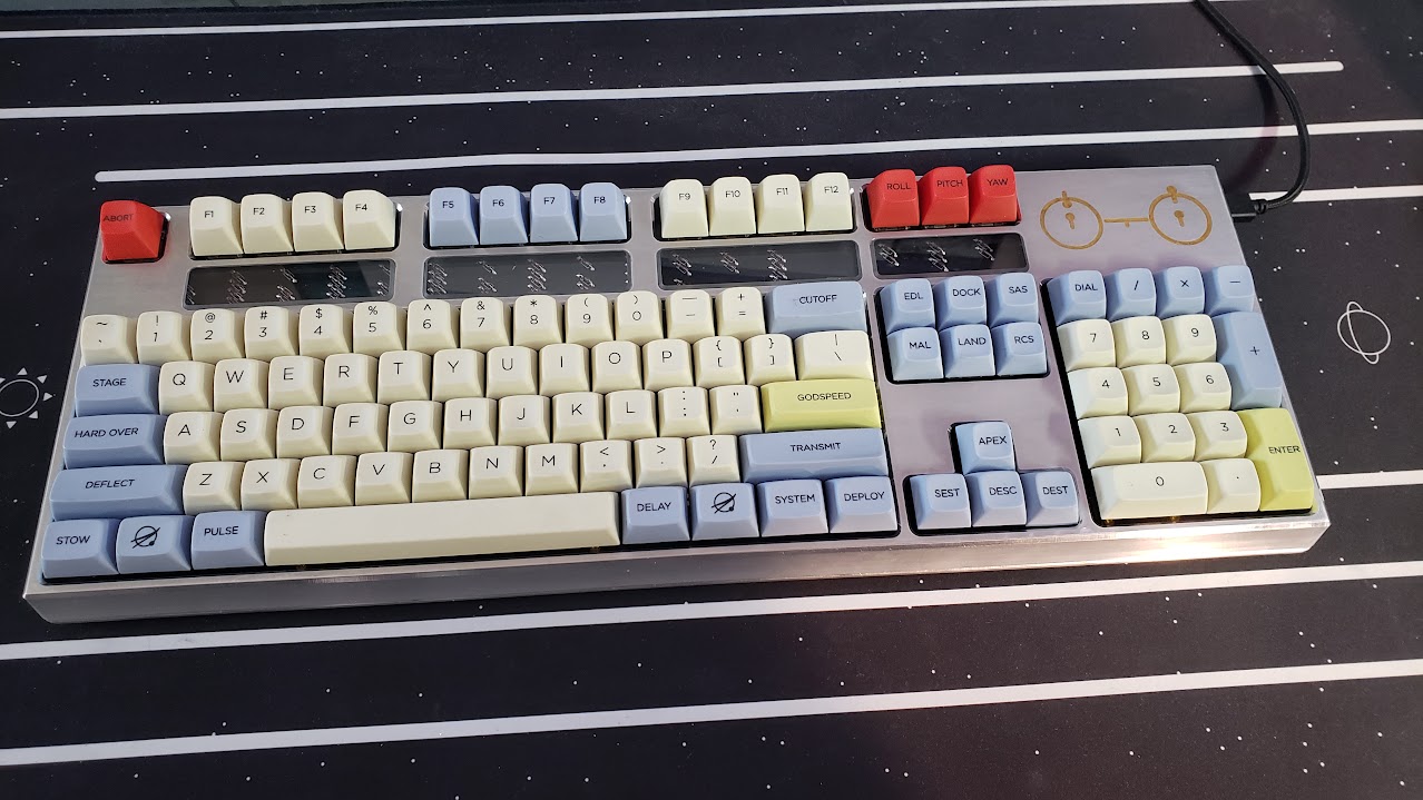
Voyager Keyboard
I designed and machined a custom enclosure for my keyboard themed after the Voyager Spacecraft’s “Golden Record.”

Background
I too used to use a “normal” keyboard. A cheap plastic membrane switch keyboard that came with a computer I purchased. In college I realized that there were better options and bought a logitech gaming keyboard. I was completely satisified by this for years until I was enlightened (corrupted?) by my discovery of the r/mechanicalkeyboards subreddit. People on there were frequently spending hundreds of dollars on customized, high quality, limited edition keyboards. It didn’t take long before I built a keyboard of my own, and while I was happy with the result, I was dissatisfied by the “building” process. My keyboard (and the vast majority of the projects on r/mechanicalkeyboards) are actually just assembled from parts purchased online, not really built from scratch.
I wanted more.
Design
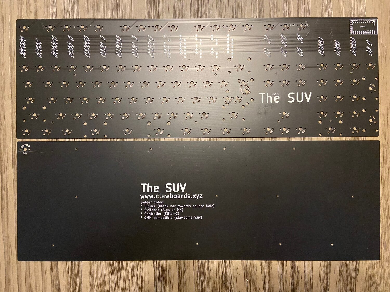
A friend / coworker of mine had a similar interest, so we bought identical keyboard PCBs from Clawsome Boards so that we could share some of the design work (I didn’t want to design my own keyboard PCB too… yet). We chose this particular PCB since it has a fairly simple layout, but the row of through-hole diodes would give some cool design options. The PCB designer was also kind enough to send us some design files to base our 3D models on.
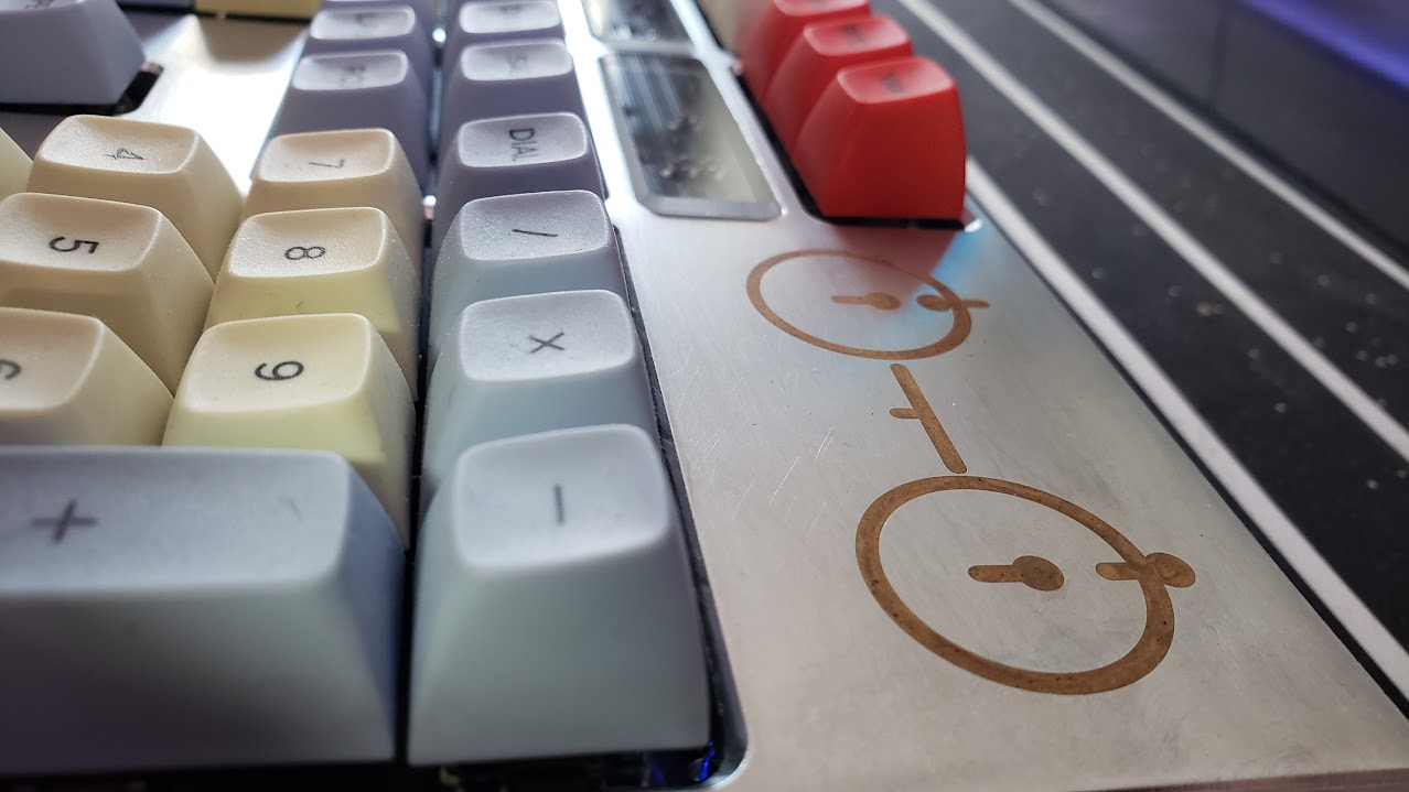
After many hours of geeking out about keyboard designs, scouring the internet for ideas, and thinking about what I had the tools and ability to actually create, I settled on a theme: the Voyager Golden Records. The records are a pair of gold-plated phonograph records that were included on the Voyager spacecraft. They included a set of diagrams that could hopefully be decoded by an alien species to learn how to play the record as well as how to find Earth. Wether this was a good idea is up for debate, but the system used to convey this information to an intelligent species with absolutely nothing in common with humans is quite clever and beautiful.
Prior to this keyboard, I had created hundreds of parts for personal projects and for the robotics company I worked at, but they were all entirely functional in nature. I had never needed a part to look beautiful as well as perform its job. I spent days looking at my ugly rectangular block of a keyboard in Fusion 360, trying to figure out why it didn’t look as pretty as I imagined it.
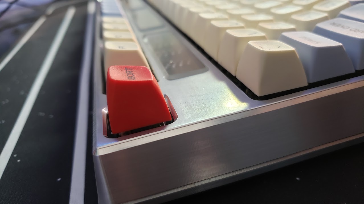
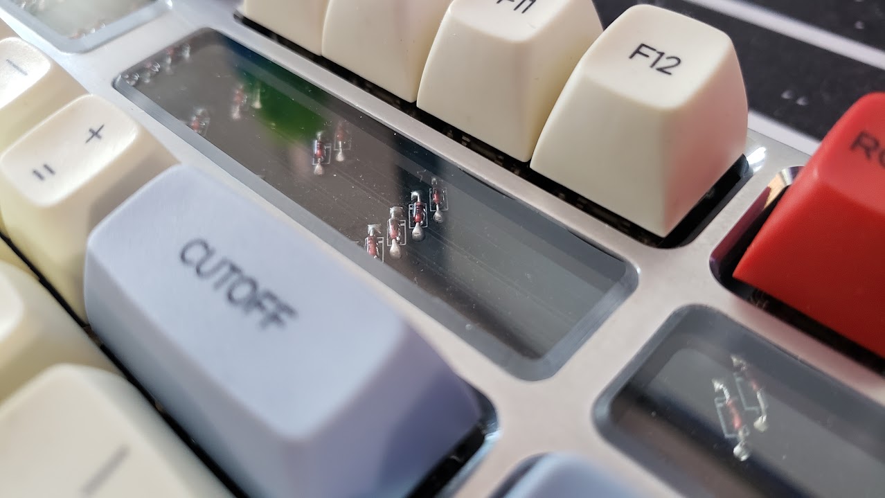
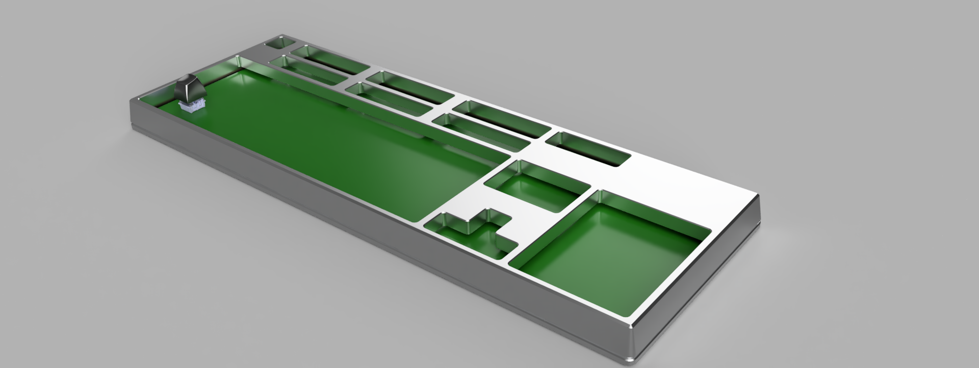
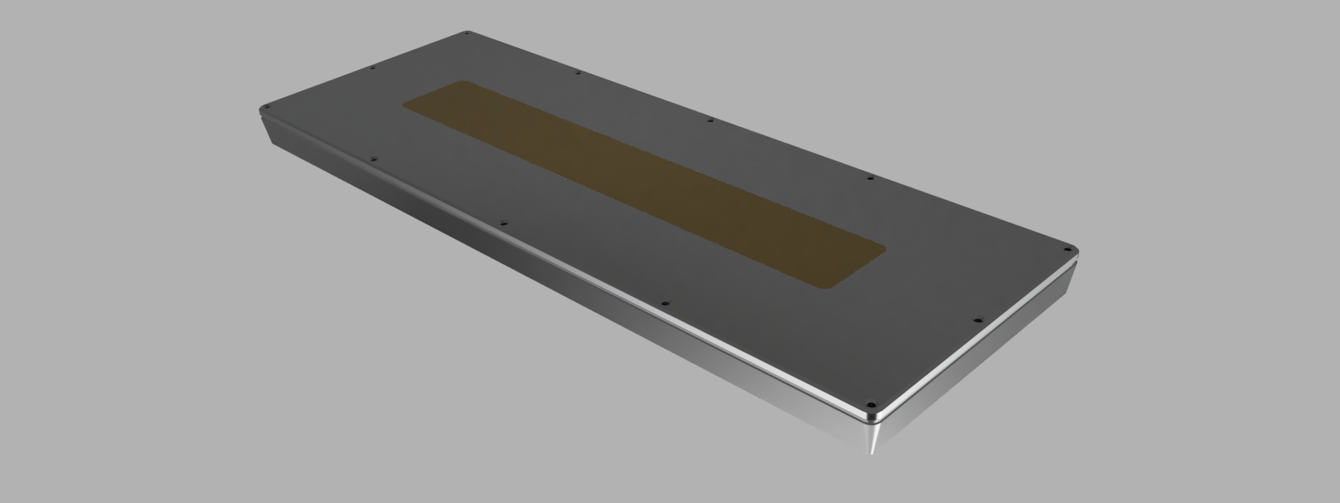
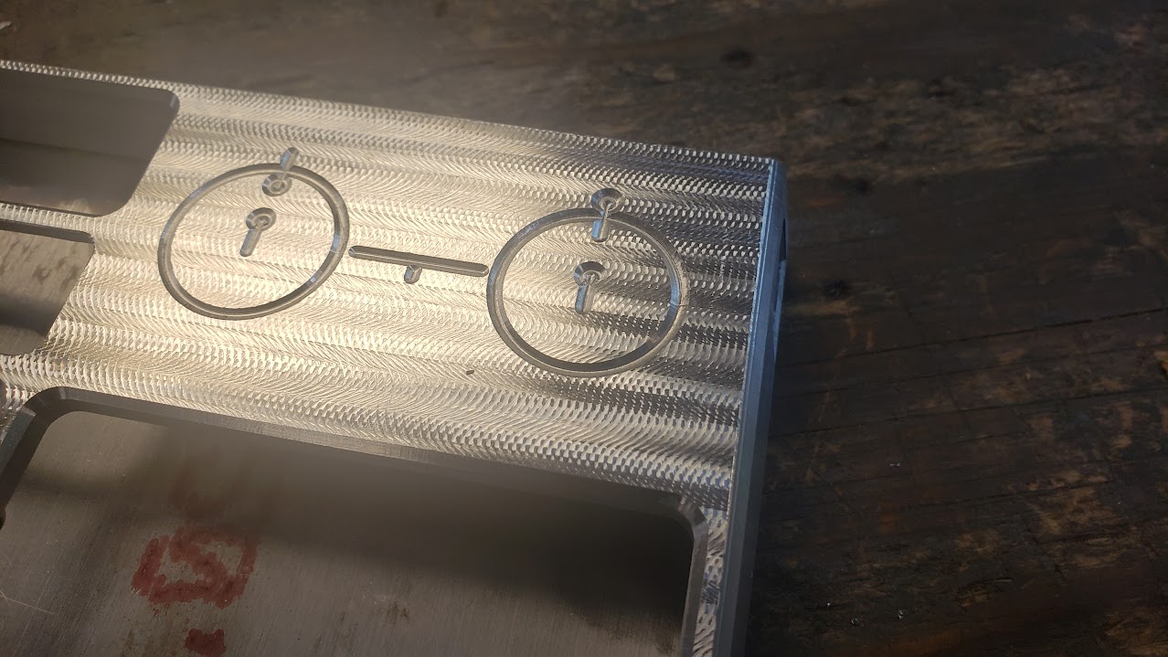
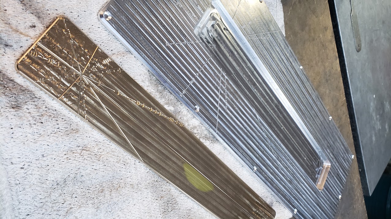
Two complete restarts and more hours spent tweaking fillet radii than I’d like to admit later, I had a design that I was happy with. It consists of three machined metal parts: a bottom plate with mounting points for the PCB, a top cover that extends around the sides and indexes with the bottom plate, and a brass bar inset into the bottom plate that adds significant heft to the case as well as being pretty to look at. Furthermore, a staple of many ultra-high-end keyboards is having the most prominent design feature on the bottom where it will never be seen. ¯_(ツ)_/¯ My design also included several clear windows to expose the diodes between the number row and function keys. I included the model of the keyswitch and keycap to ensure my proportions would look alright with keys installed.
Machining
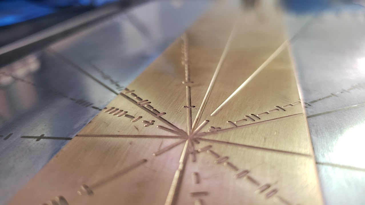
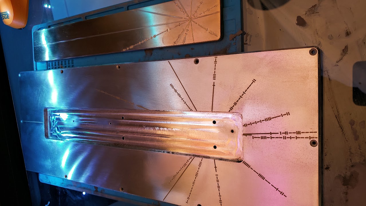
Before I committed too hard to this design, I needed to do some experiments with engraving on the CNC mill, a process I had never tried before. A quick scroll through some machining forums and a slightly longer scroll through some Fusion 360 tutorials (the “engrave” toolpath does not do what I thought it did) and I settled on using a center drill with a trace toolpath in Fusion 360. I ran this test piece on a scrap of aluminum, and then immediately forgot to take a picture of the result, so you’ll just have to use your imagination. This is not what center drills are designed for, but it works amazingly well. The shape of the tool creates a trapezoidal groove with shallow sides, allowing you to get a fairly wide line without needing to engrave too deeply, exactly the effect I was looking for.
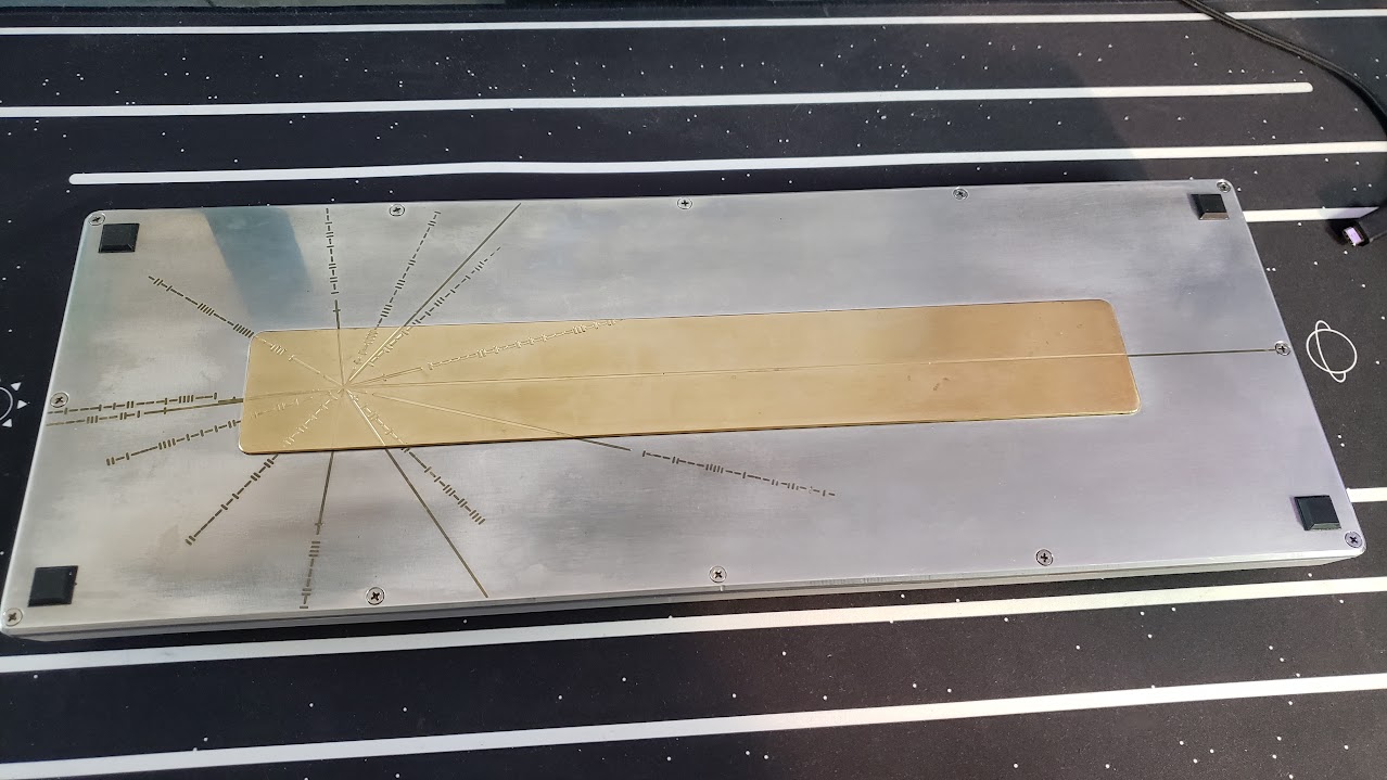
I forgot to take a picture of the test piece. Instead, here’s a picture of the final keyboard right after it came out of the mill.
A Side Note on Workholding
Since I was only making one of each part, and was doing so on evenings and weekends when my employer’s shop was available, I wanted to avoid making any fixtures if possible. This was a fun challenge, in that the order of operations became vital, and I had some too-close-for-comfort clearances between the tools and the vise.
However, the downside to doing all of the work holding without fixtures was that on several operations I was machining the face of a relatively thin cantilevered beam. In these situations the work piece would start to chatter excessively leading to abysmal surface finish.
In some cases, this effect manifested a small amount, and I was able to minimize it by tweaking the spindle speed to avoid resonant frequencies. The slight roughness remaining was then easy to buff out. But on the thinner back and brass parts, some deep chatter marks can still be seen even after extensive polishing.
If I were to do this again (which I very well might), I would absolutely make fixtures for the thin parts. Even though I know I can solve all of the workholding problems, the rigidity provided by the fixtures would be a massive help in eliminating this issue.
Finish Work
Once all the pieces had been machined, it was time for a little bit of elbow grease.
I started with 100-grit sandpaper to remove the major machining marks then slowly worked up to 3000-grit for the final polish. This process took longer than I care to remember (should have just bought an orbital sander) and my desk still has smudges of aluminum sanding grime in impossible to reach crevices.
I also had to clean up some of the chamfers that had chatter marks as a result of the workholding techniques described earlier. To sand these down while keeping the sharp chamfer corners, I 3D printed a simple 45-degree sanding jig to hold a perfect angle.
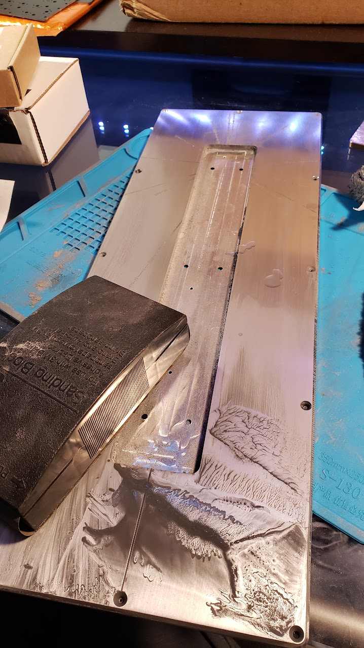
My initial plan was to simply polish it to a shine and be done with it, but I felt like the the engraving didn’t stand out well enough against the polished aluminum.
While browsing the interenet I discovered a technique for doing inlay work, usually in wood, by mixing metal powders with resin. Soon I was the proud owner of some metal-compatible slow-cure epoxy and small bags of brass and mica powders. I used the brass to hopefully match the tone of the brass weight on the backside, with a bit of mica mixed in for sparkle.
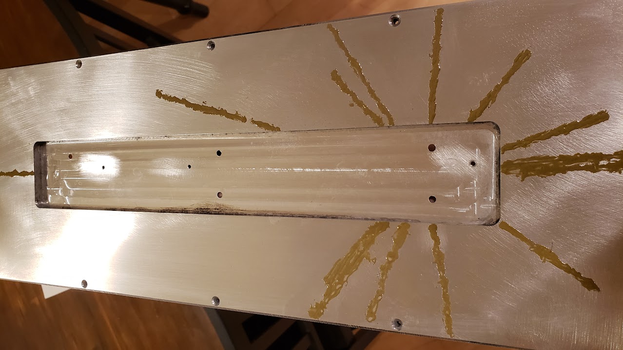
I applied the inlay as a thick paste over the engraved grooves, then it only took a little bit (ok maybe more than a little) more sanding to level it with the rest of the board.
The last parts to make were the clear windows between the number and function keys. I made these late at night all in one sitting and forgot to take a single picture of the process so you’ll just have to imagine.
I cut out slightly oversized rectangular acrylic blanks with a laser cutter and attached them to a sacrificial base board with machinable fixturing wax. I machined them in a small desktop CNC mill using downcutting tools to avoid pulling the parts away from the wax.
The only thing left was to take glamour shots and post them online to get validation from strangers on the internet.
The Photoshoot