Touch Sensitive LED Fader Bank
My teammate and I created a new style of touch-screen (ish) fader to use in computer audio applications.
Background
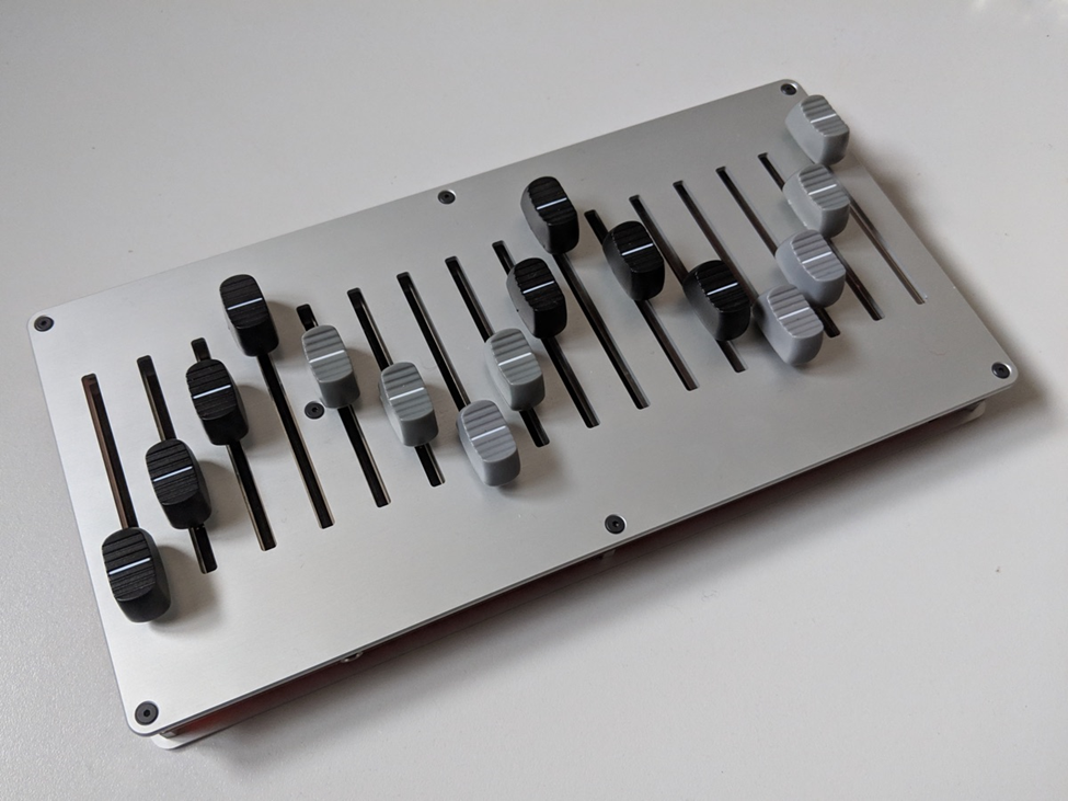
People working with music on their computer will often have a variety of analog input devices to more easily control the sound. The most basic example is volume sliders to control the relative volume of various tracks, but in modern music production software, those sliders can be mapped to any attribute such as tempo or the attributes of a certain effect.
These sliders are called “faders” in the industry, and a device that includes several faders is called a “fader bank.”
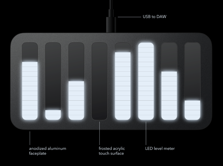
Now imagine a fader bank which, instead of physical sliders, used touch sensors with rows of LEDs used to display the current position.
Now stop imagining and check out what we built!
My partner, Brady Hartog, and I created this fader bank for our ECE 5780 Embedded Systems Design class. We ended up going a bit overboard relative to the class requirements, but we have no regrets and love our final product.
Here’s the story of how we built it.
Prototyping
The class we were in gave all of the students (well, we really bought it with our class fees but let’s pretend it was free) a STM32F072B Discovery board to learn throughout the class. The most unique feature of this particular development board is the inclusion of a capacitive touch slider. (That series of white bars covered by acrylic at the bottom of the board).
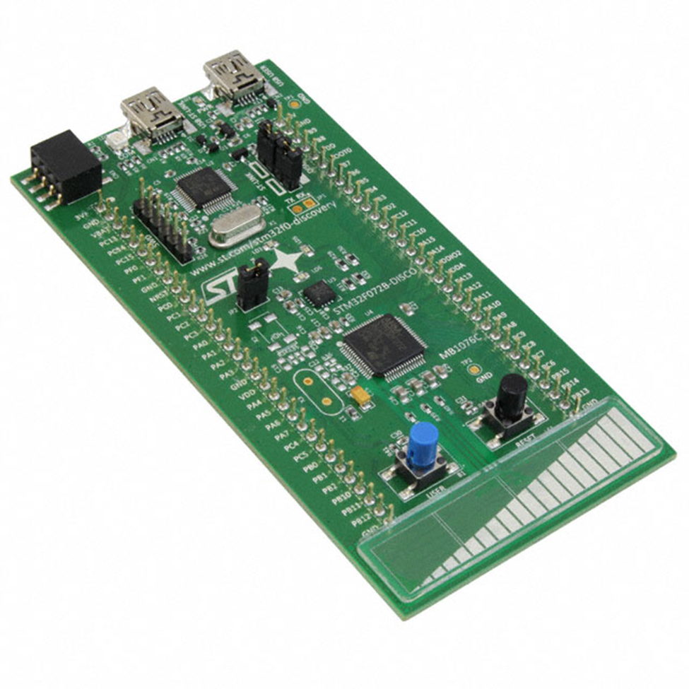
Capacitive touch sensing can be done with many microcontrollers, but getting it to work can be a real pain. The STM32F072B microcontroller has a hardware peripheral which makes touch sensing a breeze, and the development board included a code demo to play around with as well.
Brady had the idea of using this capability to create a novel MIDI controller design. I was sold from the moment he mentioned it. Our initial concept included eight channels instead of four, but was otherwise similar to what we ended up with.
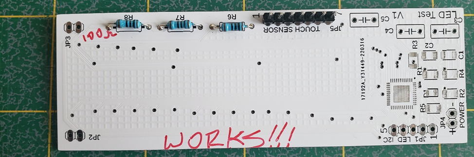
Neither of us had worked with this many individually-controlled LEDs before let alone the touch sensors, so we decided it would be prudent to design a practice PCB before going to the final design. The practice board included a single touch sensor of my own design, a circuit to run the LED driver chip we planned on using, and two rows of LEDs of different sizes so we could test which looked better.
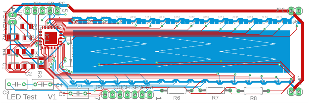
One row of header pins (green) is to communicate with the LED driver chip over I2C. The other row is to read the touch sensor. Jumpers were also included so we could power each row of LEDs separately if desired. R6, R7, and R8 along the bottom were chosen to be through-hole components instead of SMD because they are used to tune the behavior of the touch sensor and I planned on changing them out multiple times.
I was extremely happy with how useful this board turned out to be. Perhaps most importantly, it showed us that the footprint for the LED driver chip that we got from DigiKey’s website was simply wrong. Secondly, having this board which I could modify with abandon was vital to figuring out the touch sensing.
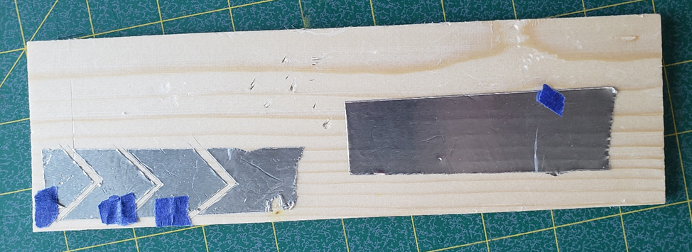
At some points of my testing, I was so confused by the behavior (or lack thereof) of the test board, that to keep myself from going crazy, I removed the board from the equation entirely. I created this simple analog out of conductive tape to convince myself that touch sensing was really possible, my board just had problems.
I slowly brought myself back to modern technology by first soldering directly to the pads of the sensor. I thankfully had the foresight to buy more than one of these boards from the manufacturer.
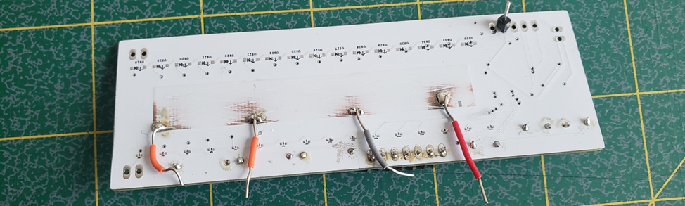
Eventually I fixed my mistakes, most of which were software related, not actually problems with the PCB, and created the first working touch sensor of our own design.
If you’re interested, this YouTube video shows a debugger on my computer displaying a value captured from the touch sensor on the test board.
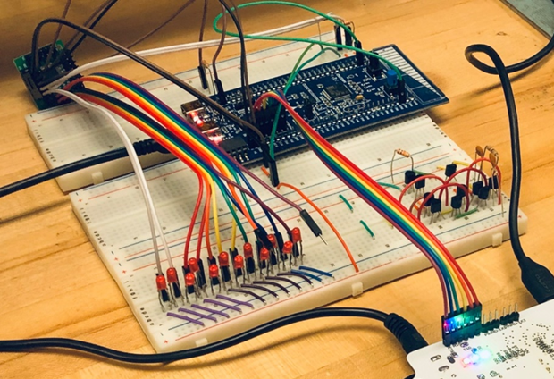
Since the footprint of the LED driver chip was incorrect, we built a replica circuit on breadboards to verify the circuit and start developing the code.
In parallel to the PCB and software debugging, I experimented with various methods of diffusing the light from the LEDs. My favorite effect came from scoring a piece of frosted acrylic partway through and applying a light-blocking ink in the scored lines. The ink would prevent the light from bleeding in one direction, creating an effect of discreet light bars very similar to our initial design concept. I won’t bother with pictures as these effects don’t come across on camera well. Unfortunately, the tight deadlines imposed on us by the class schedule meant that I wasn’t able to spend the time necessary to make this method work as consistently and I wanted. Instead, we settled on using a single layer of milky translucent acrylic to diffuse the light.
Final Design
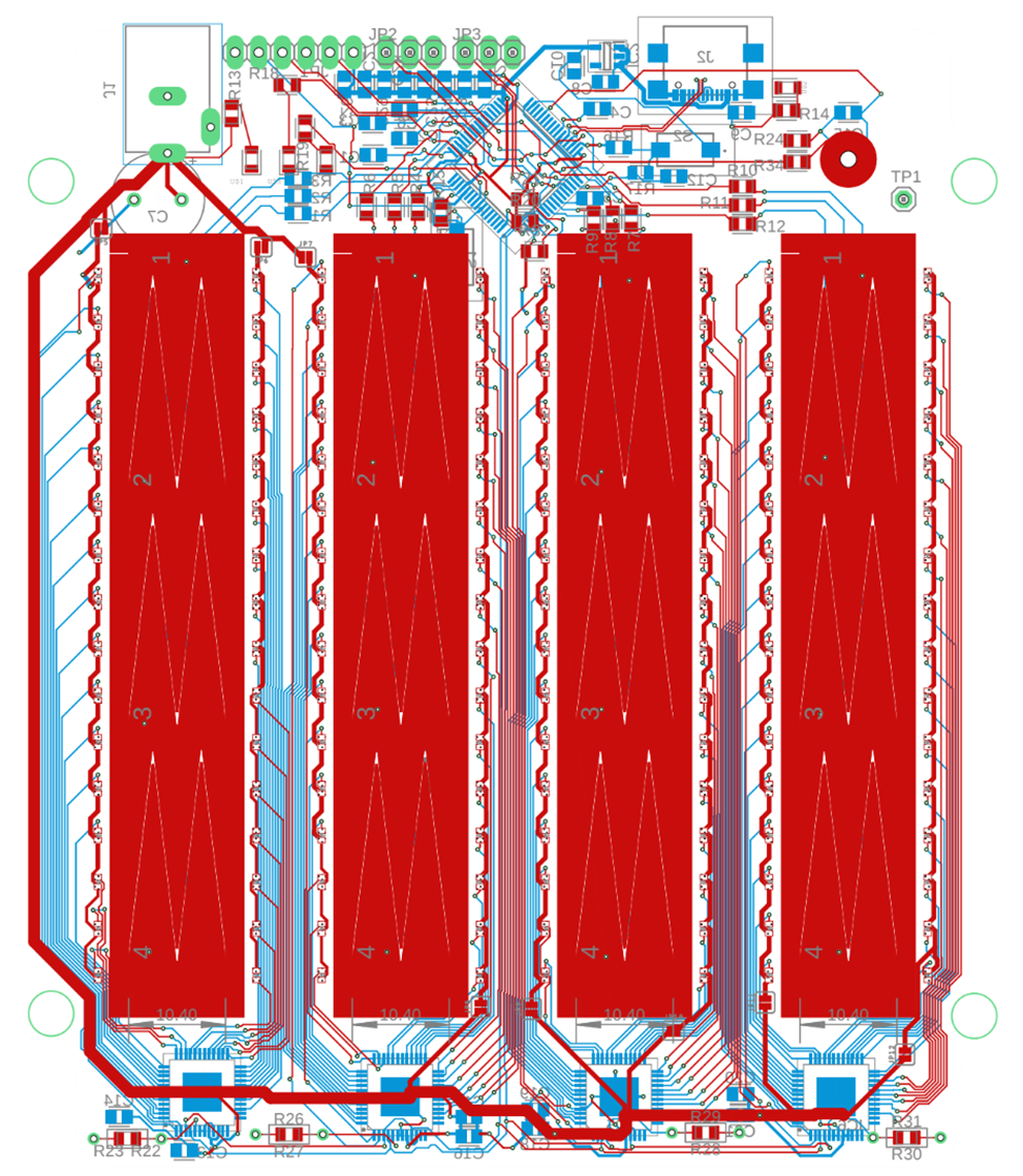
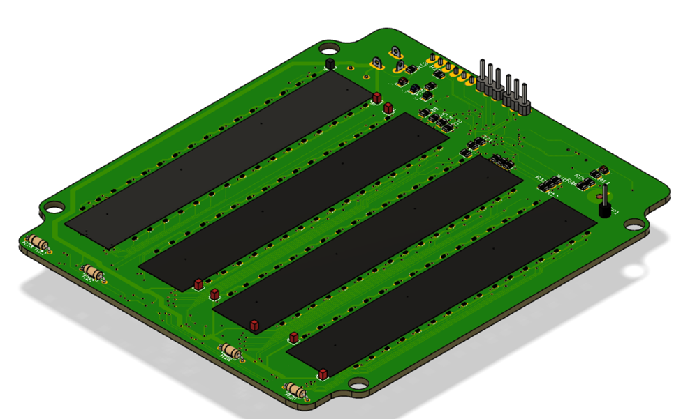
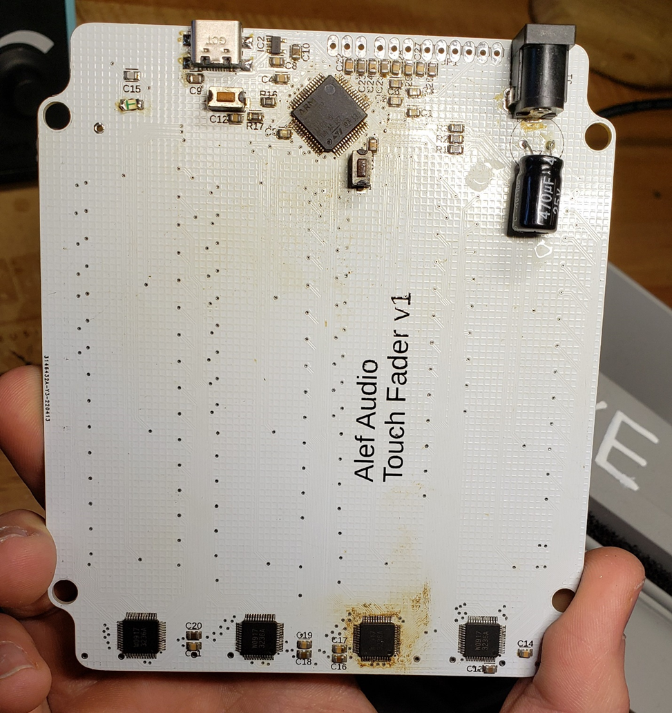
Finally, we were able to order the final PCBs. We decided to use a simple two-layer board because we wouldn’t have time to order another board before the end of the semester if something was wrong. The two-layer board would allow us to manually rework the board and change connections if needed. We were also unsure of how internal traces would affect the touch sensors. The downside of the two-layer board is that the overall device needed to be slightly bigger to accommodate all of the traces. Because we only had once chance to get it right, we chose to avoid placing any components or traces behind the touch sensors to avoid noise.
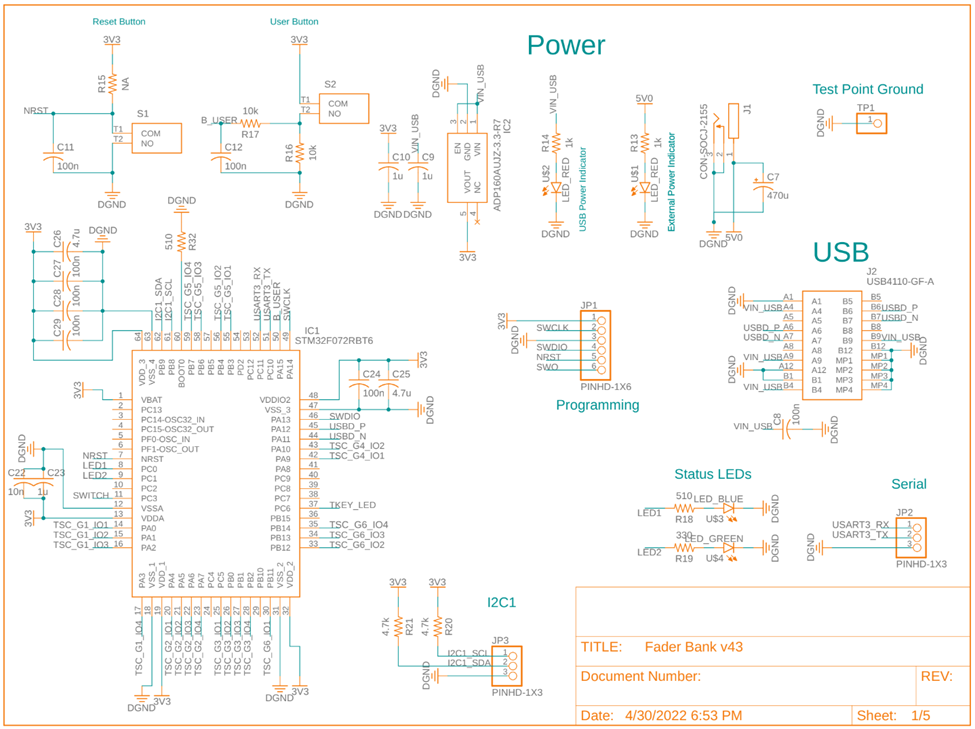
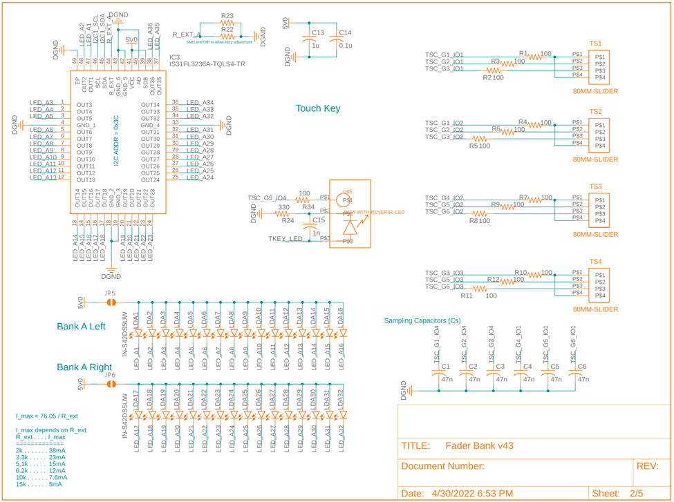
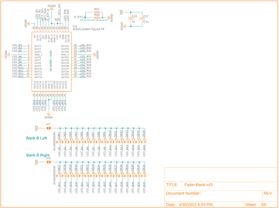
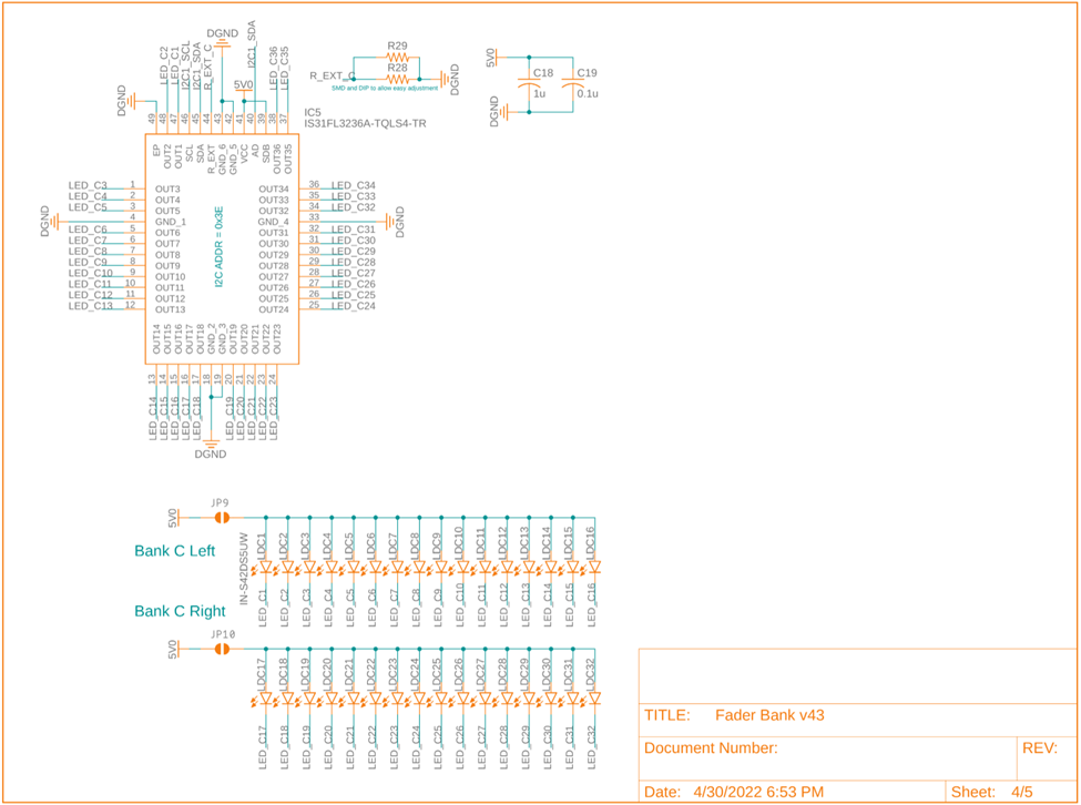
Creating the circuits for the final board wasn’t difficult as it was mostly just four copies of the test board. However, getting the components to fit within the size that we wanted while still having enough room for routing traces took many hours of tetris-ing parts around the board. Full schematics and layout diagrams are included at the bottom of the page.
All of the components were ordered from Mouser except for one: the microcontroller itself. We were taking the class during the infamous chip shortage, meaning every MCU had months-long lead times. We had planned ahead for this, so with minimal shed tears, we cannibalized our trusty development boards and transferred the microcontrollers to the new PCBs.
Neither of us had any experience with reflow soldering and solder stencils, but this seemed like a great opportunity to learn. In particular, we learned that getting the temperature settings just right on the reflow oven is very important…
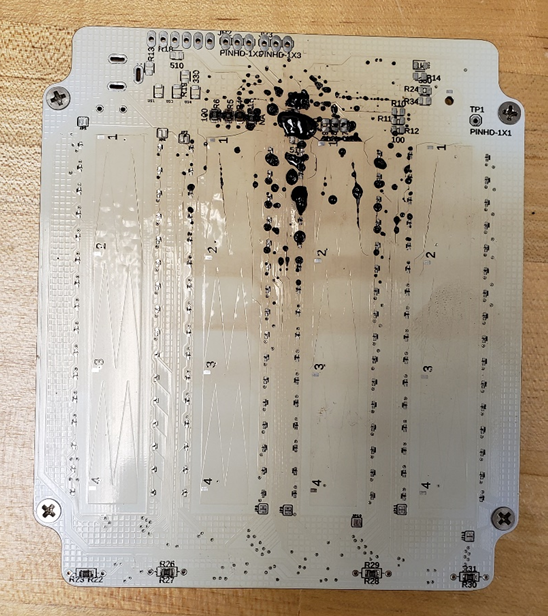
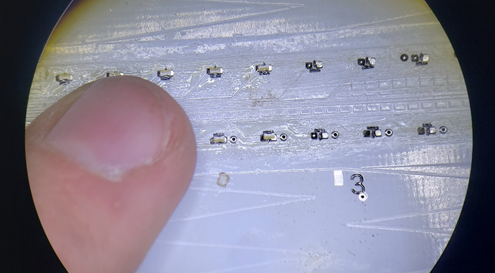
We also learned that dealing with 0402 size components by hand is an absolute nightmare. Especially when you have 300 of them.
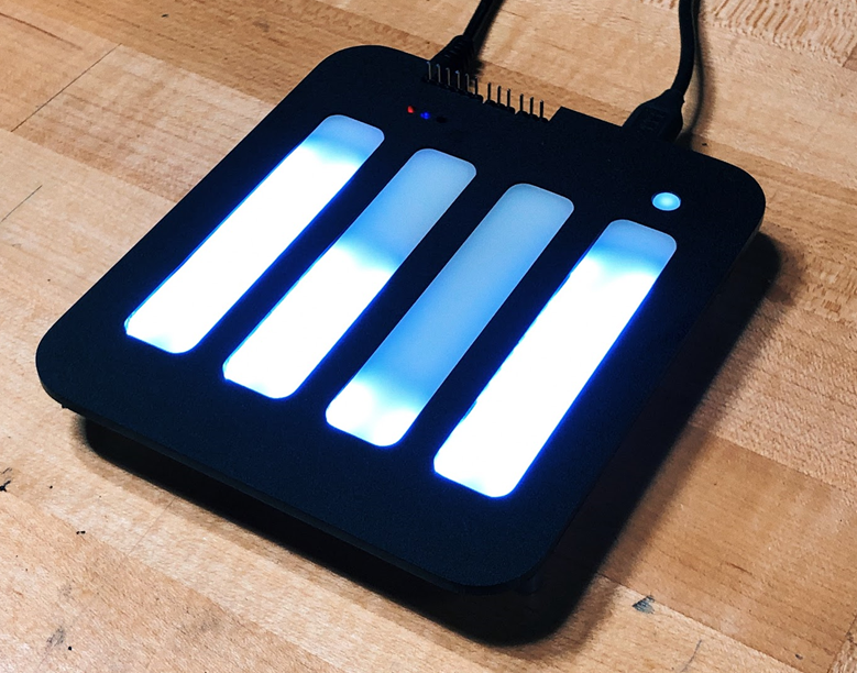
And the fully assembled board!
Software
All of this hardware development is only half of the story. We had been busy on the software side too.
For development we had been using the Keil MDK toolchain in the Keil μVision IDE. STM32CubeMX initialization code generator was used to… well… generate initialization code.
Because the device’s functionality was fairly simple, we decided not to use an RTOS. Instead, we used a hybrid event model with a main loop doing data processing and several interrupt handlers communicating with the I2C, USB, and Touch Sensing peripherals.
We developed a custom library for communicating with the LED drivers since their initialization, and even the steps necessary to simply toggle a single LED, were quite complicated. That was wrapped by another custom library to abstract away specific LEDs and MIDI parameters. At the top level, the programmer can simply use a get and set method to control both the MIDI parameter and the LEDs.
We used many external libraries as well. Touch sensing, I2C, UART, GPIO, and USB interfaces all came from the official STM32 HAL libraries. The MIDI implementation came from Sam Kent on Github
You can see the full repository on Github here..
All that was left was to package it up and make a demo video! If you just want to see the device in action, skip to 11:05.
Appendix
Here are the full schematics and PCB layout.