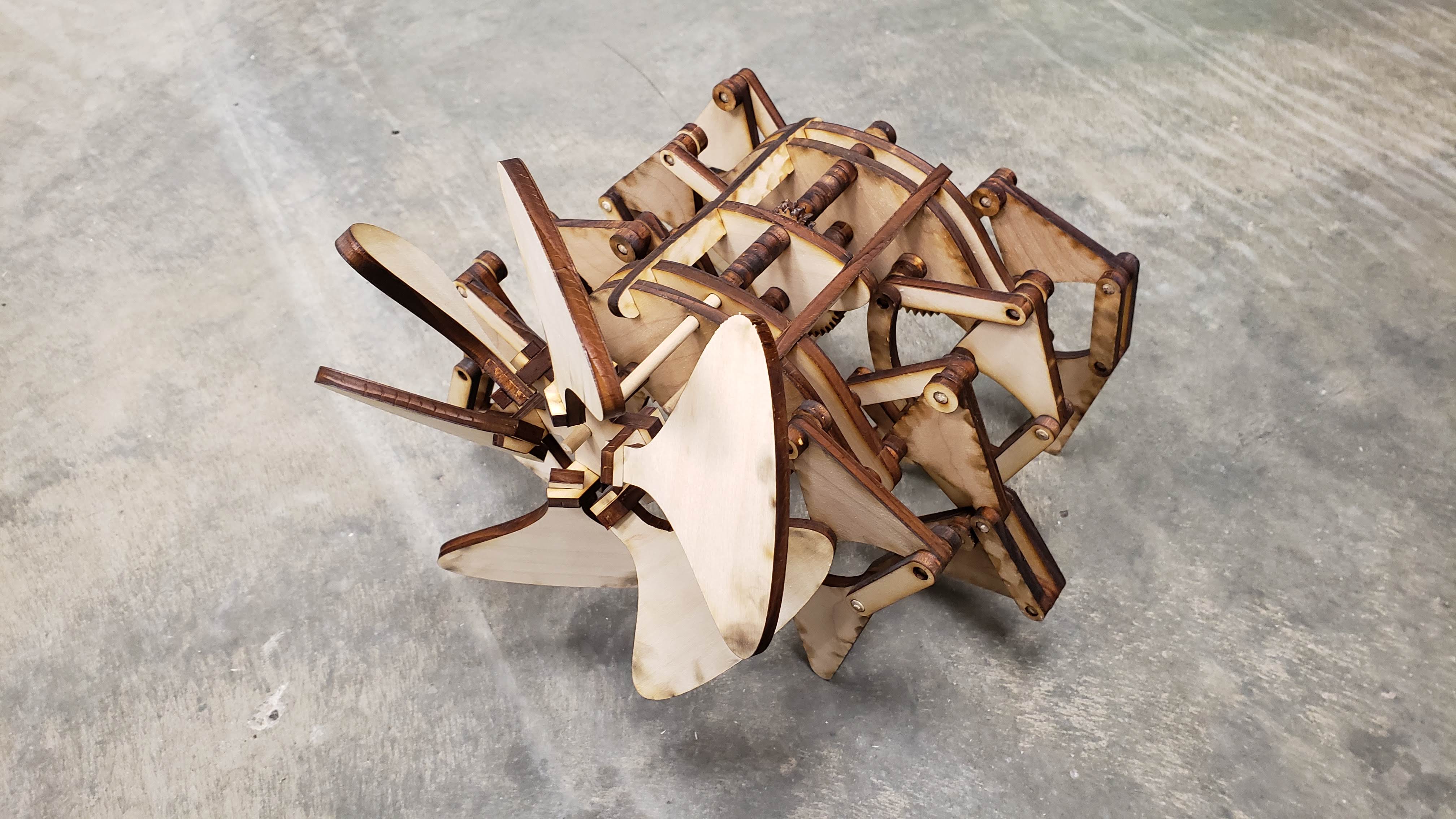
Strandbeest Mechanical Walker
I designed and manufactured a laser-cut kit for a Strandbeest mechanical walking machine then hosted a workshop for six students to assemble their own.
I work as a “Tool Mentor” at the Lassonde Make Space (see more here) on the University of Utah campus. I get to help students create their own projects and teach them how to use the tools we have available. Every semester (pre-covid of course), each mentor hosts a workshop where students can learn a specific skill or create a project.
For the Spring 2020 semester, I drew inspiration from Theo Jansen’s Strandbeests (I highly recommend that you check them out) and the tributes made by various creators on the internet to make a laser-cut mini strandbeest kit.
From the start, I knew this would be more of a manufacturing challenge than a design challenge. Many people have built walkers based on this mechanism before; there’s even whole websites dedicated to the details of how they work which I could turn to if I ever got stumped by the mechanics.
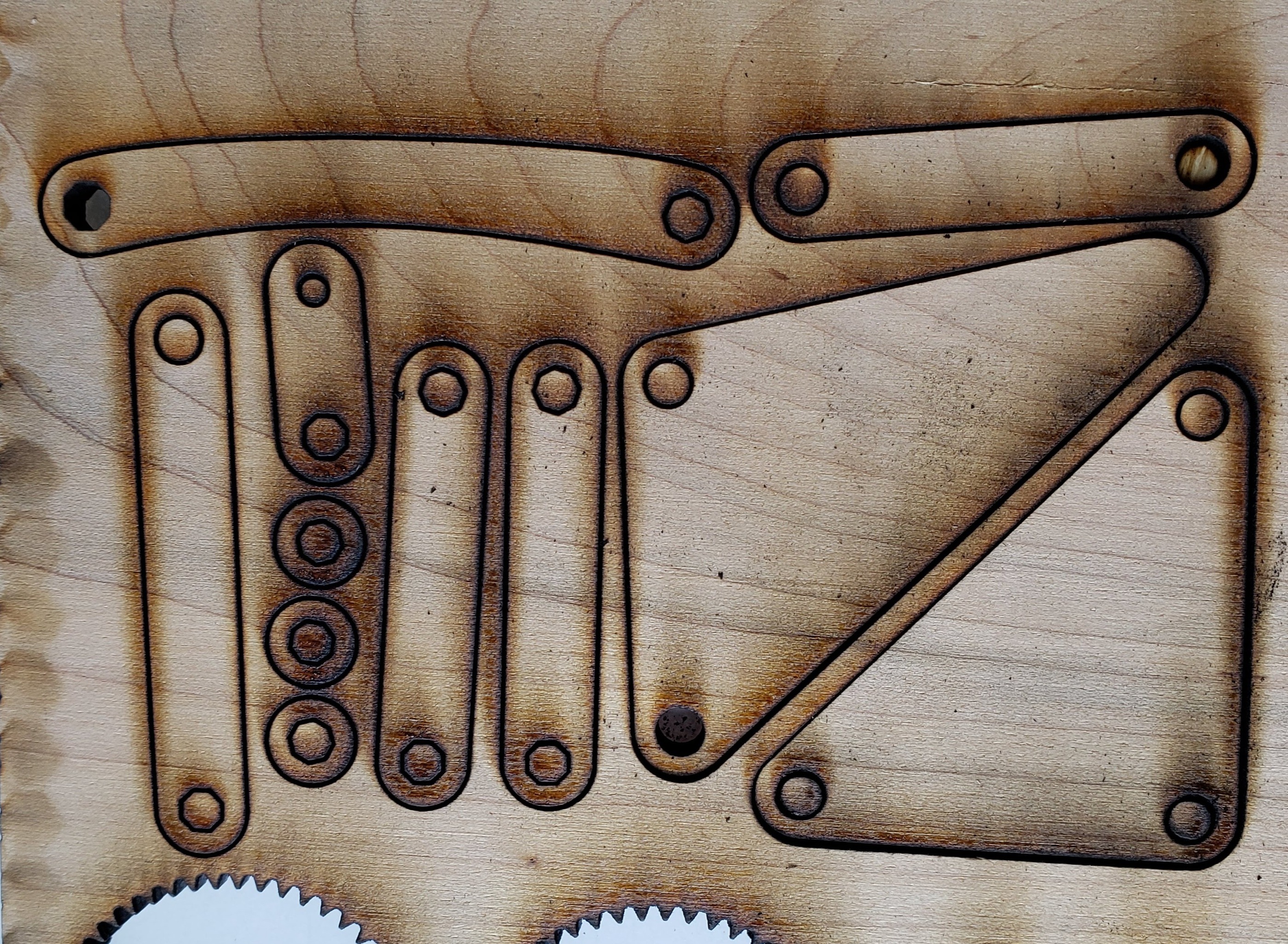
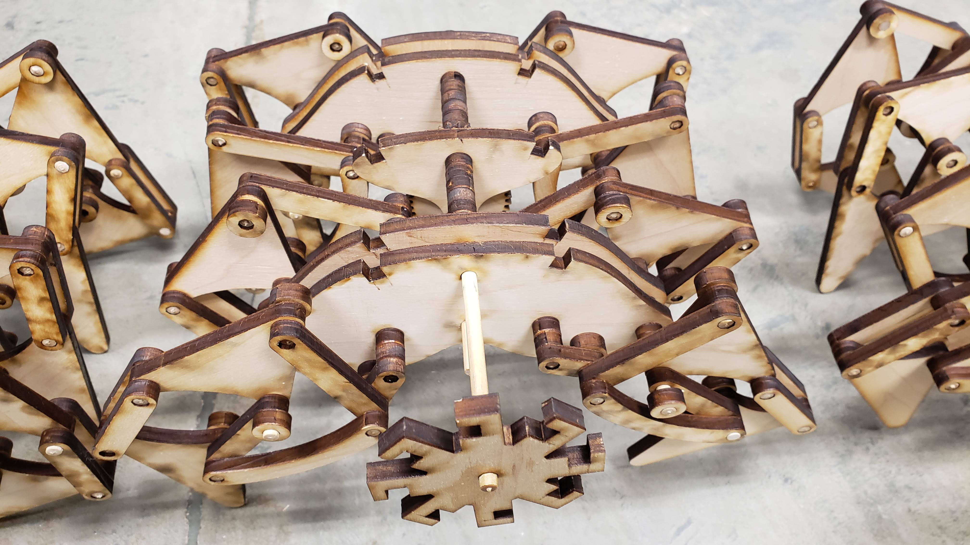
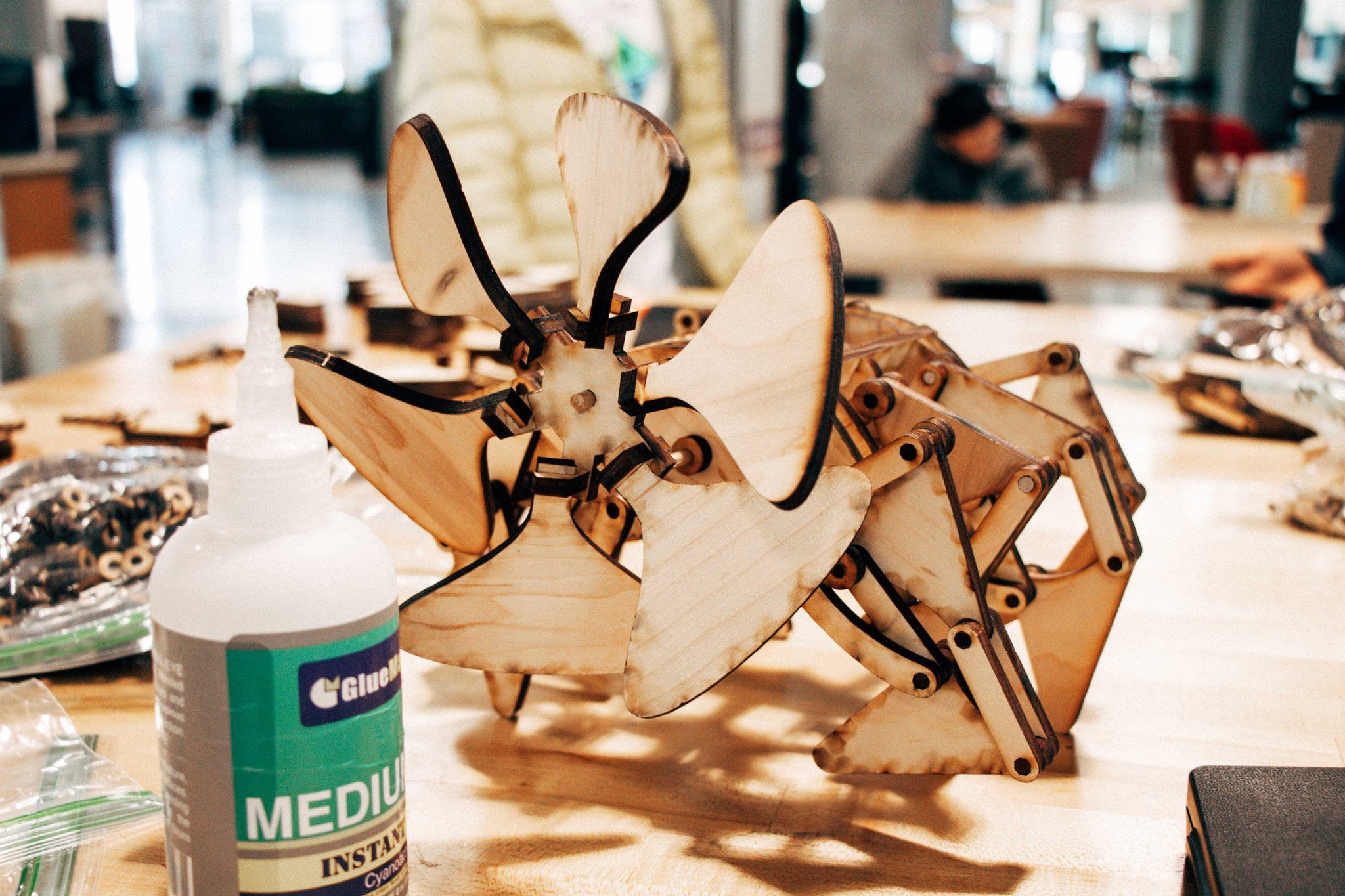
I started with the basic leg mechanism, governed by the Jansen Linkage and was able to whip up a design fairly quickly in Solidworks.
Having never laser cut large batches of parts at once, I immediately ran into issues on how to efficiently nest the parts on a sheet. Of course I could manually place them but I knew that with the revisions I would have to make, that would quickly become impractical. The student edition of Solidworks has limited manufacturing abilities, but I was able to create a secondary flat configuration of the parts that would work for now.
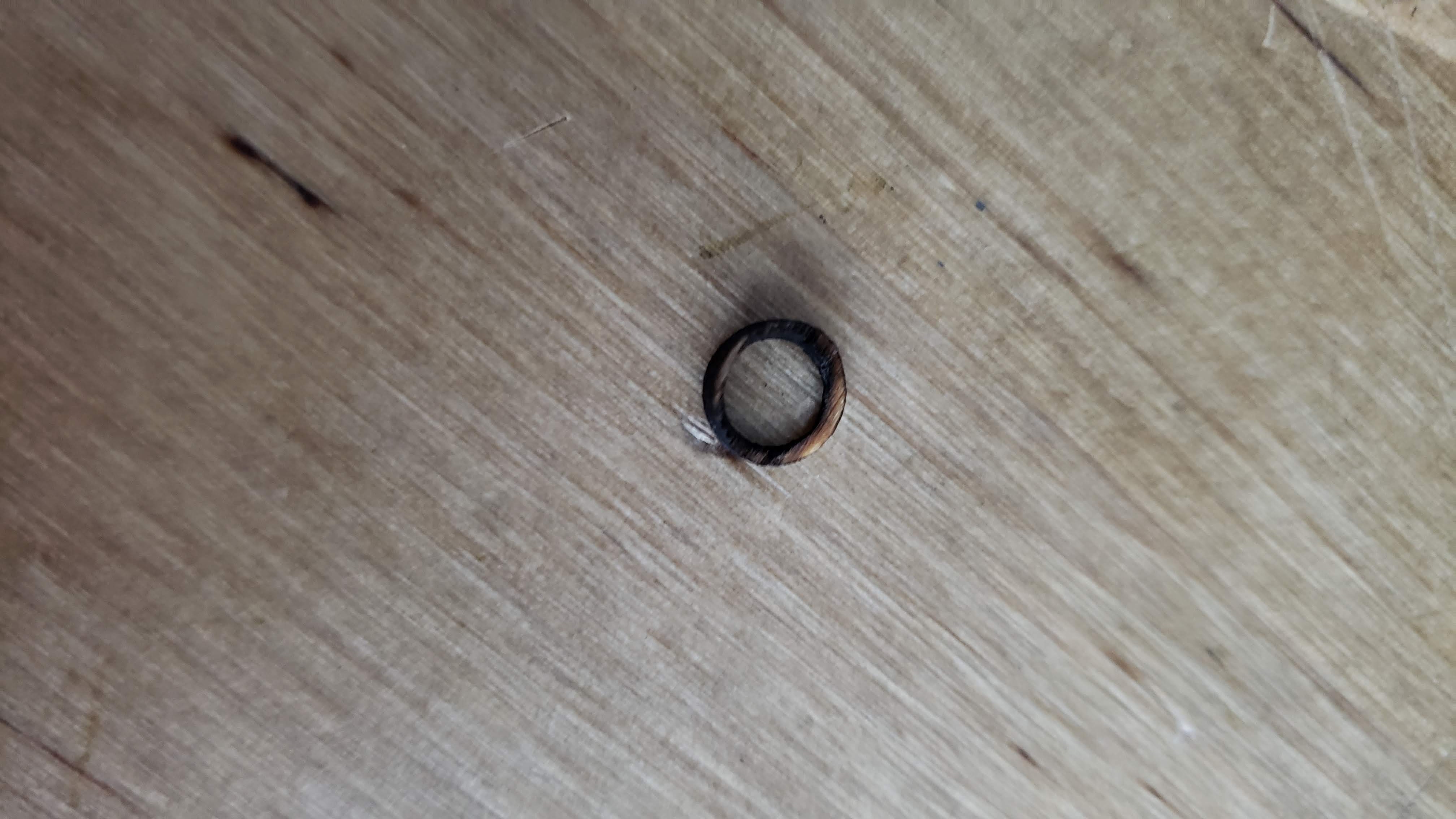
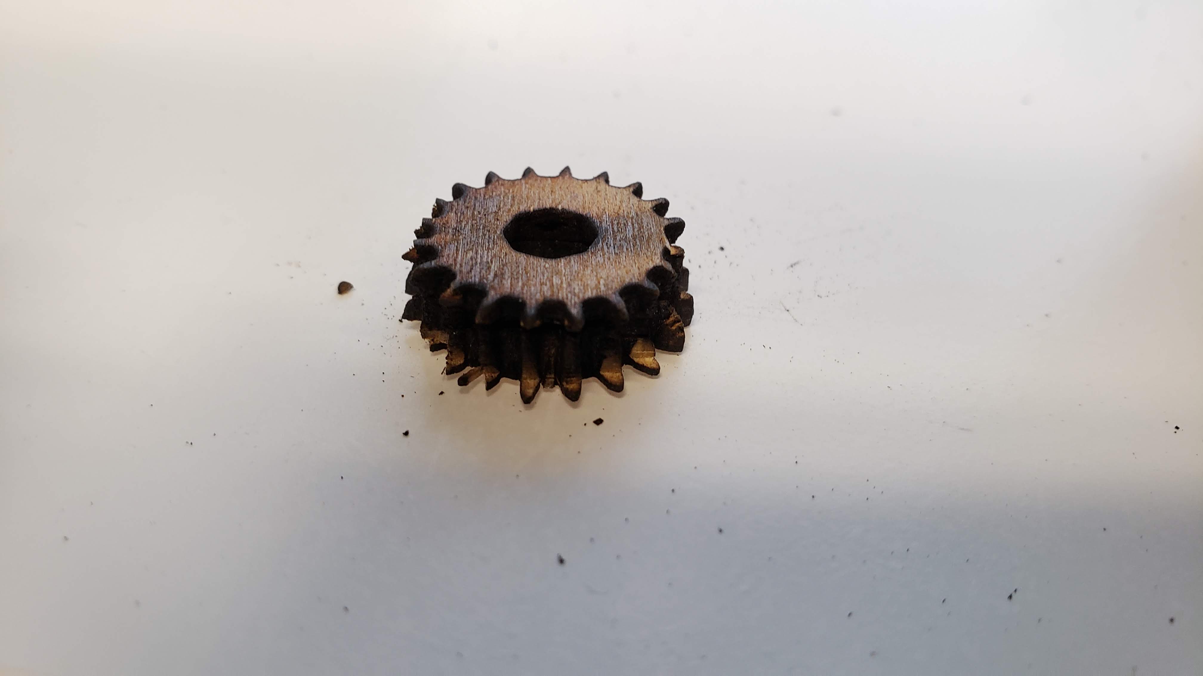
The mechanism worked as I hoped, but there were many issues. The press fit parts were all wrong, either too loose or too tight. The gear teeth were too fine, causing them to break easily. The laser power was too high, charring the fine details inconsistently. The spacer rings were so thin that they were almost entirely burnt away by the laser.
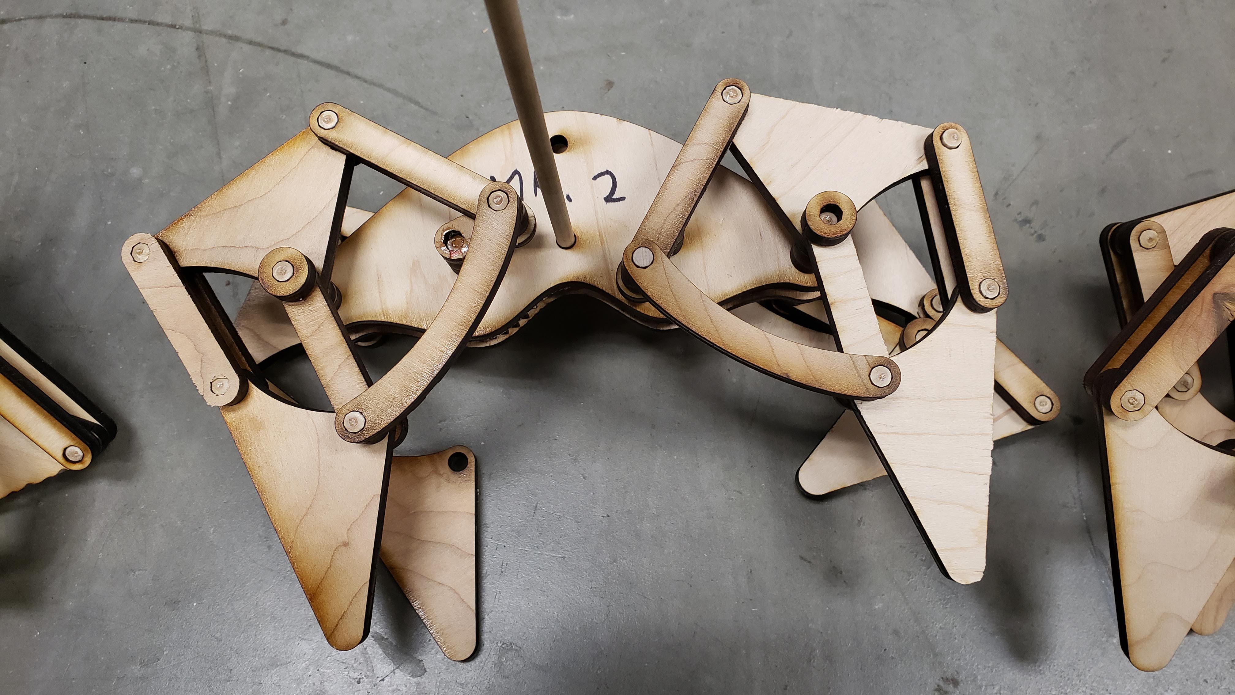
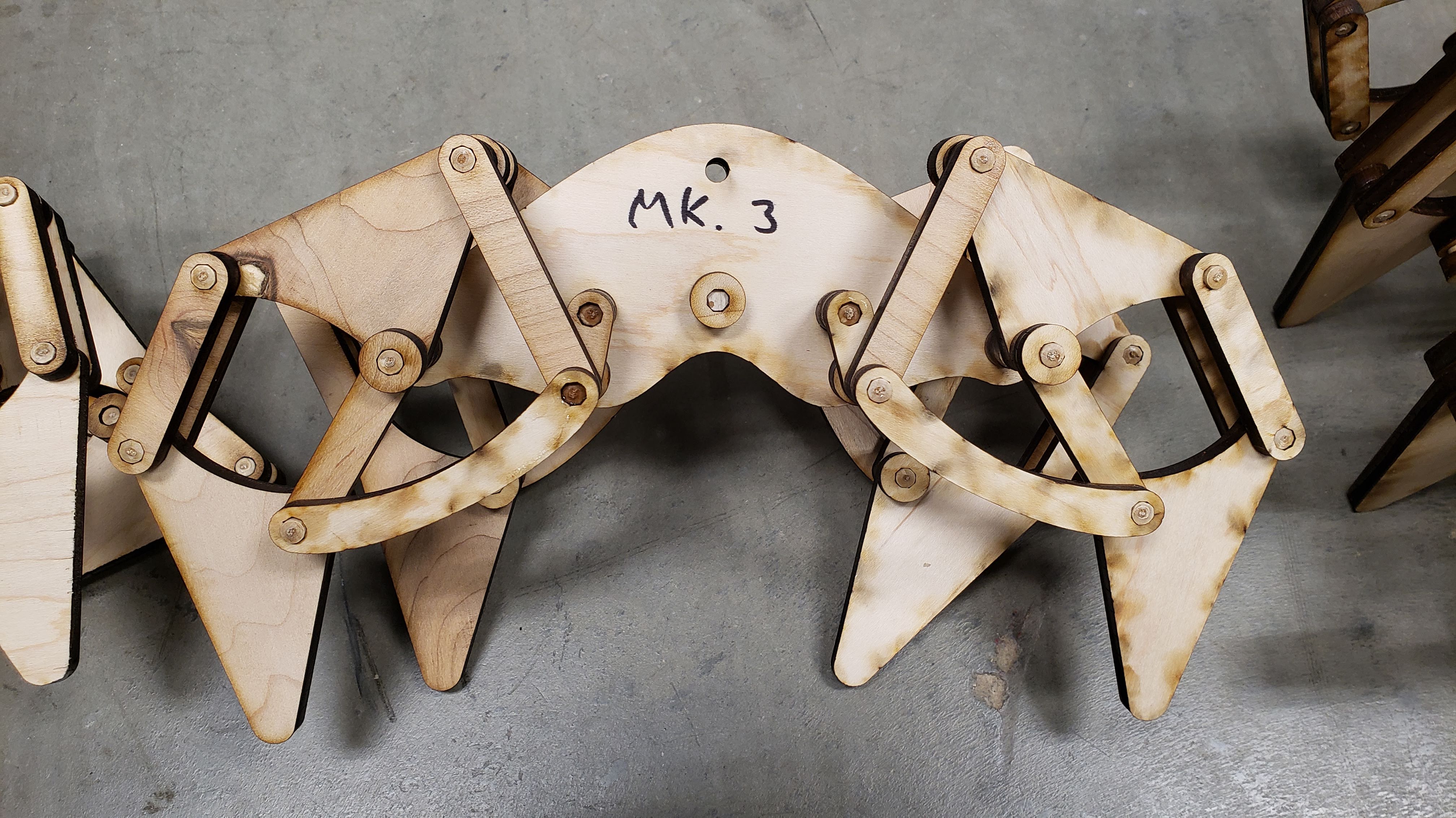
These issues were all simple enough to solve, but as with any detailed project like this, every iteration would reveal almost as many problems as it solved. I’ll spare every detail, but here is a brief montage of the six full versions I assembled, not counting the countless revisions to individual parts.
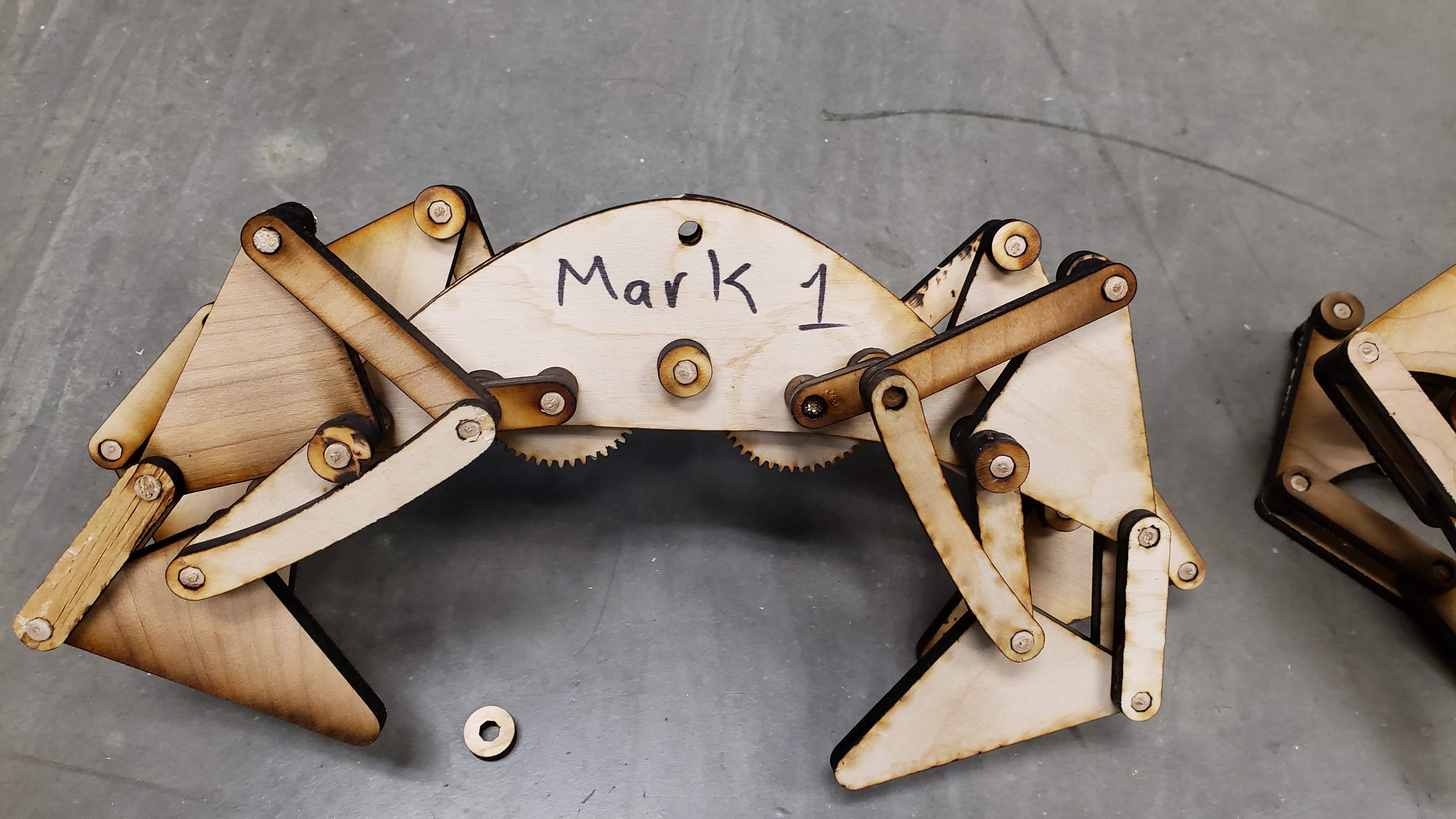
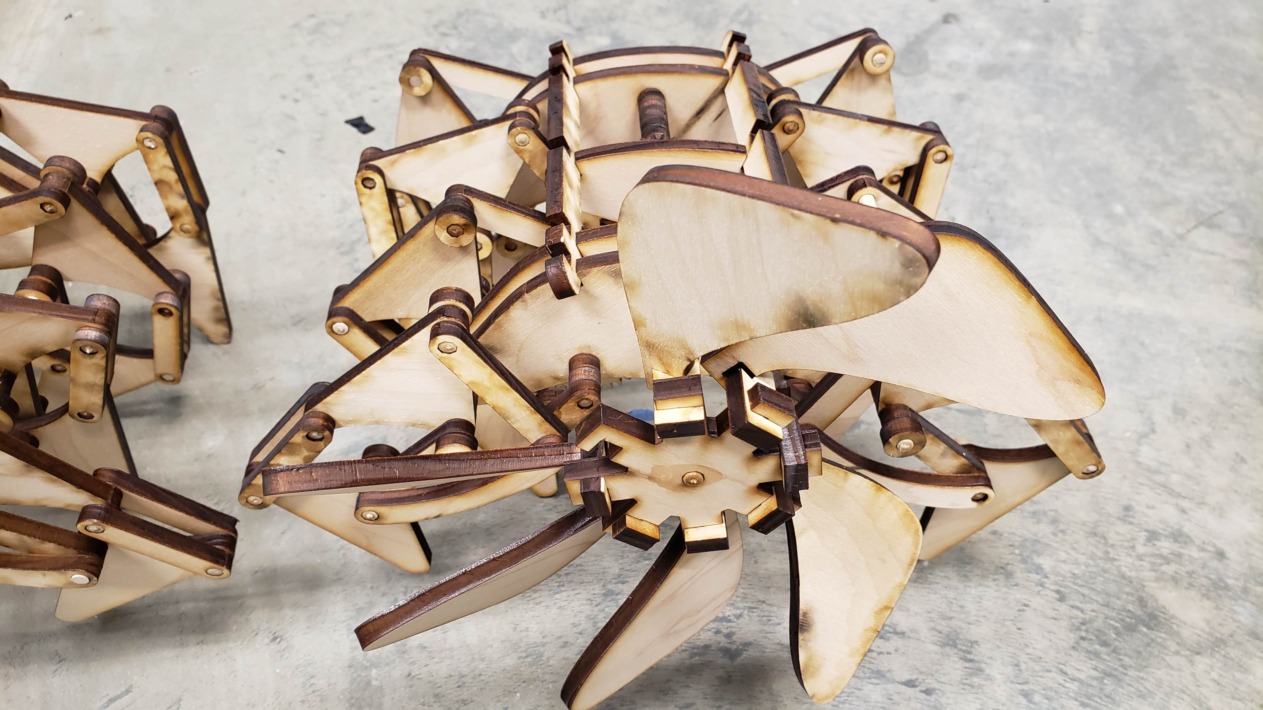
Once I had reached V4, I started to work on the manufacturing and assembly processes. Building a single machine when you are the designer is one matter, but making ten and teaching others to assemble them is another matter entirely.
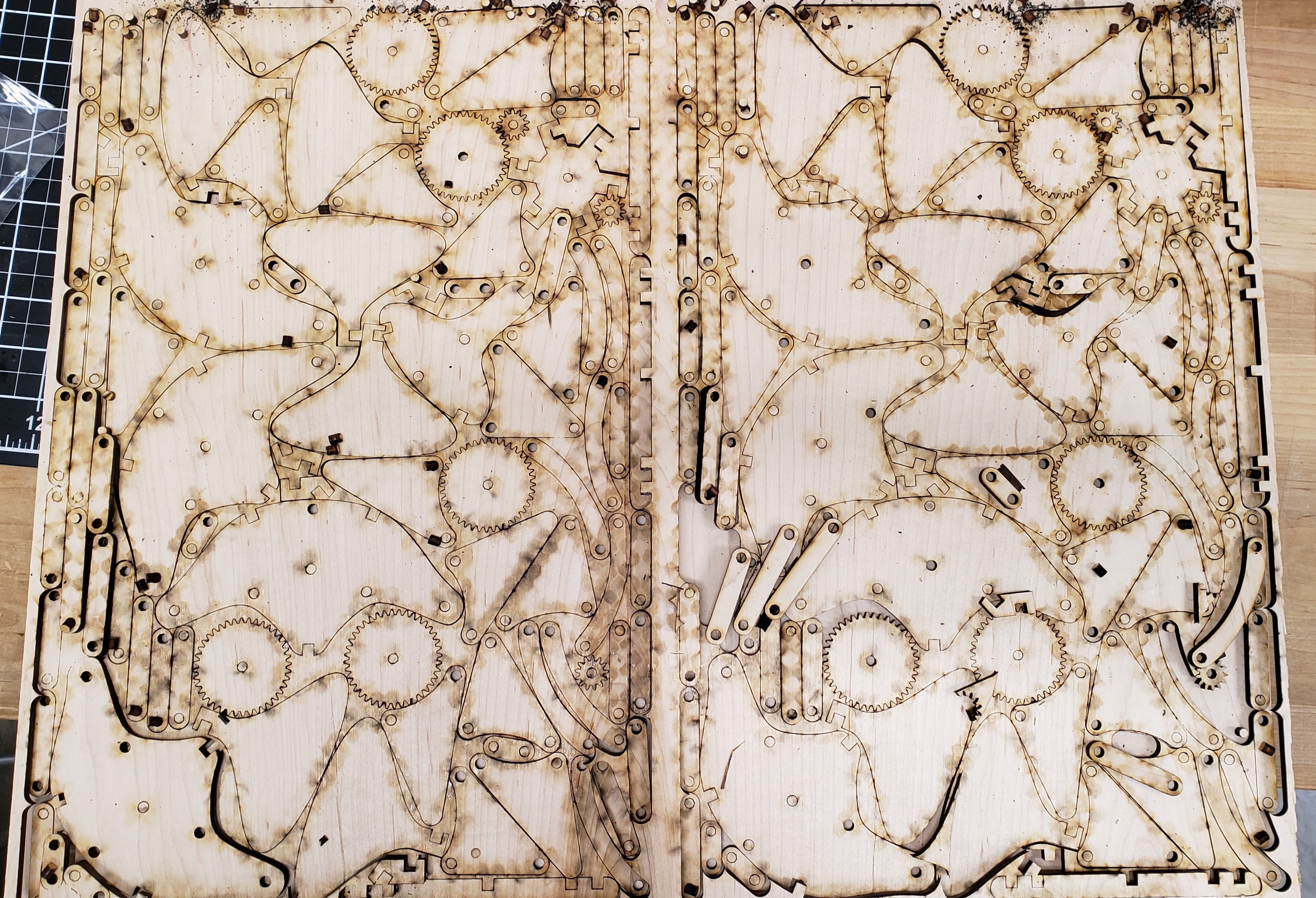
By this time I had discovered an online service that would nest vector drawings as well as a Solidworks macro which allowed me to instantly export the flat face of each part in the assembly as a DXF. With these two tools, it became fast and easy to make revisions to the model and export it to a laser-cuttable format. I was able to optimize the nesting in a way that allowed me to cut two complete machines from a single sheet of plywood stock.
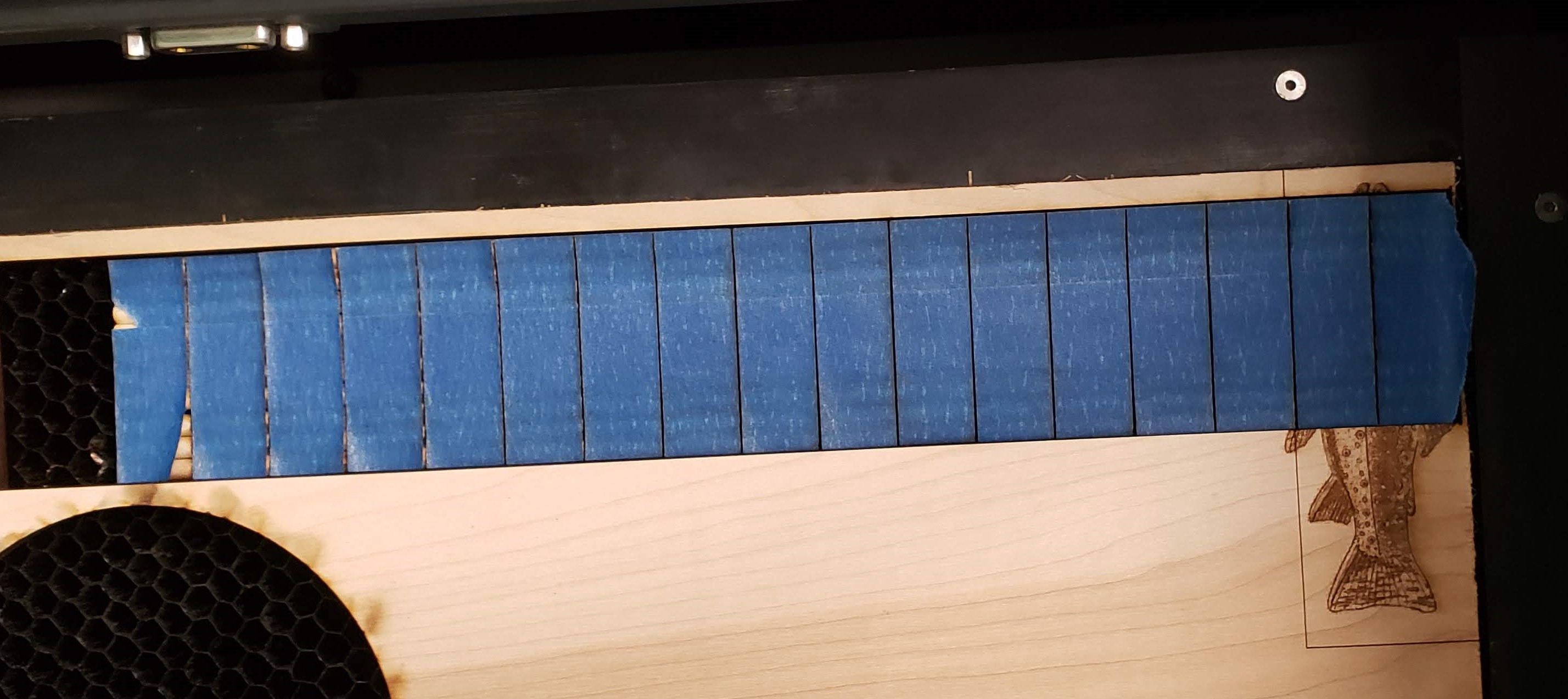
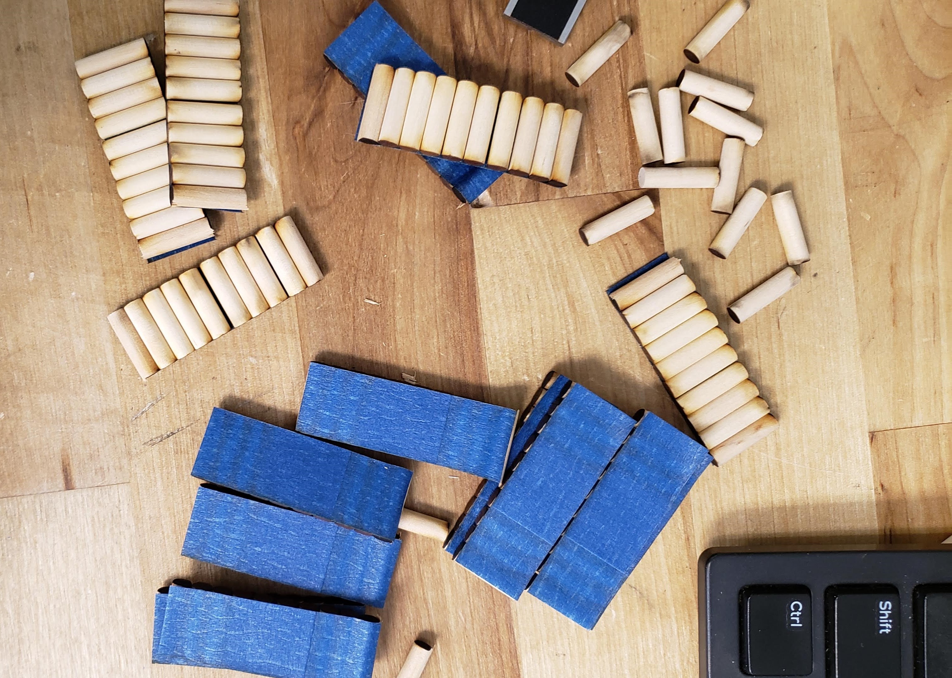
Up to this point, the dowels holding the plywood parts together had to be cut manually with a ruler and utility knife. A timer and a quick calculation told me that it would take an entire day to cut enough dowels for the workshop, a process I was not looking forward to. Also, I was not happy with the inconsistent lengths and occasional poor cuts the manual process created.
A few hours of experimentation later and I had created a jig out of scrap wood for the laser cutter which held rows of dowels, allowing me to cut hundreds to exactly the right length in just a few minutes. I laid masking tape over the top of the dowels to make it easy to remove them from the cutter without letting them drop through the laser cutter honeycomb.
As I put each improved version together, I took careful notes on my assembly process. Which modules needed to be completed first, which parts were most tricky to assemble, which joints needed a bit of glue to prevent slipping, which joints needed a bit of wax to prevent binding, etc.
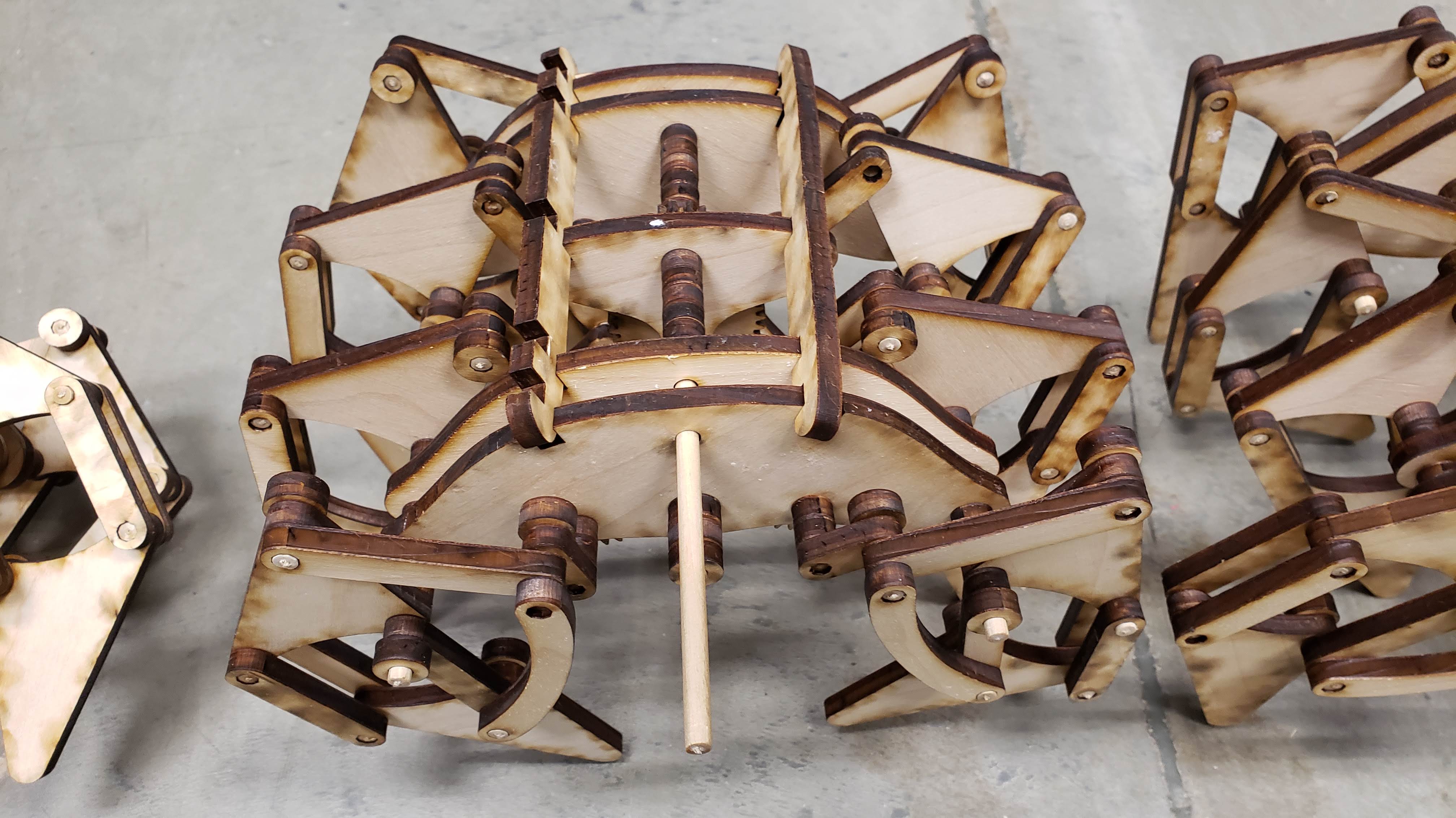
The first complete machine I assembled took five hours just by myself. By the time I had reached V7, in under three hours I was able to assemble my own, as well as coach my test subjects (thanks mom and little brother!) through building their own.
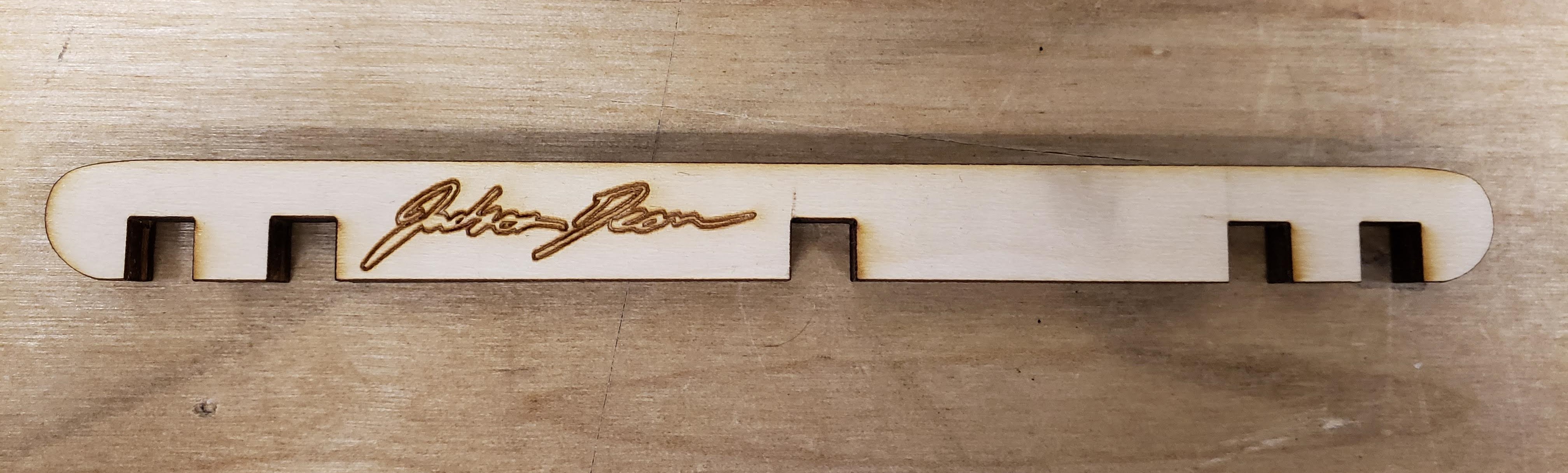
The last change to make was to add my engraved signature to the “spine” of the machine and it was complete. Then it was only a few hours to cut the parts, divide the pieces for each kit into individual bags, and make signs to advertise the workshop. I was ready.
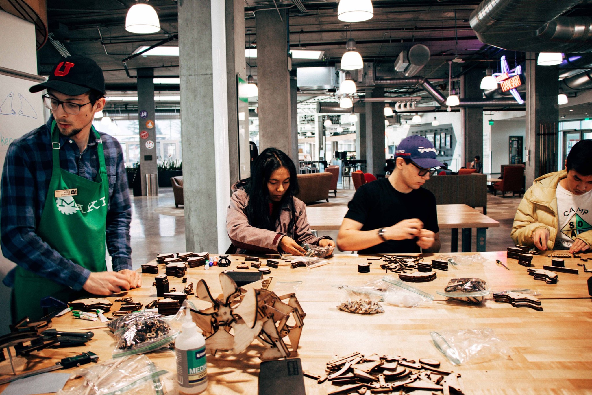
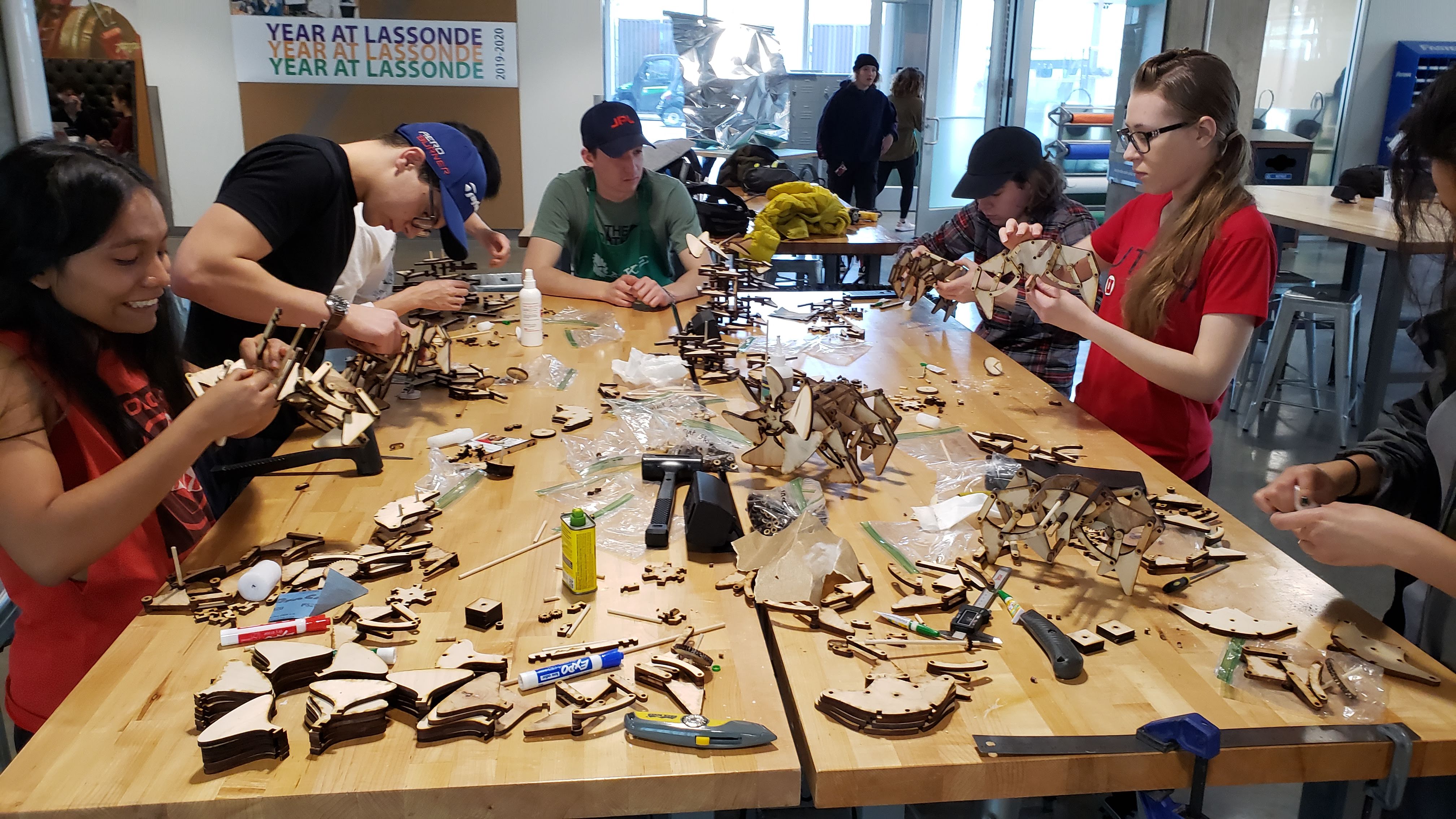
Here’s a few pictures of the workshop itself. Six people ended up coming, which could not have been more perfect. Any more and we would have had to split up to different tables and it would have been much more difficult to keep everyone on the same pace.
(Note that the workshop was conducted in early 2020, thankfully right before the pandemic started.)
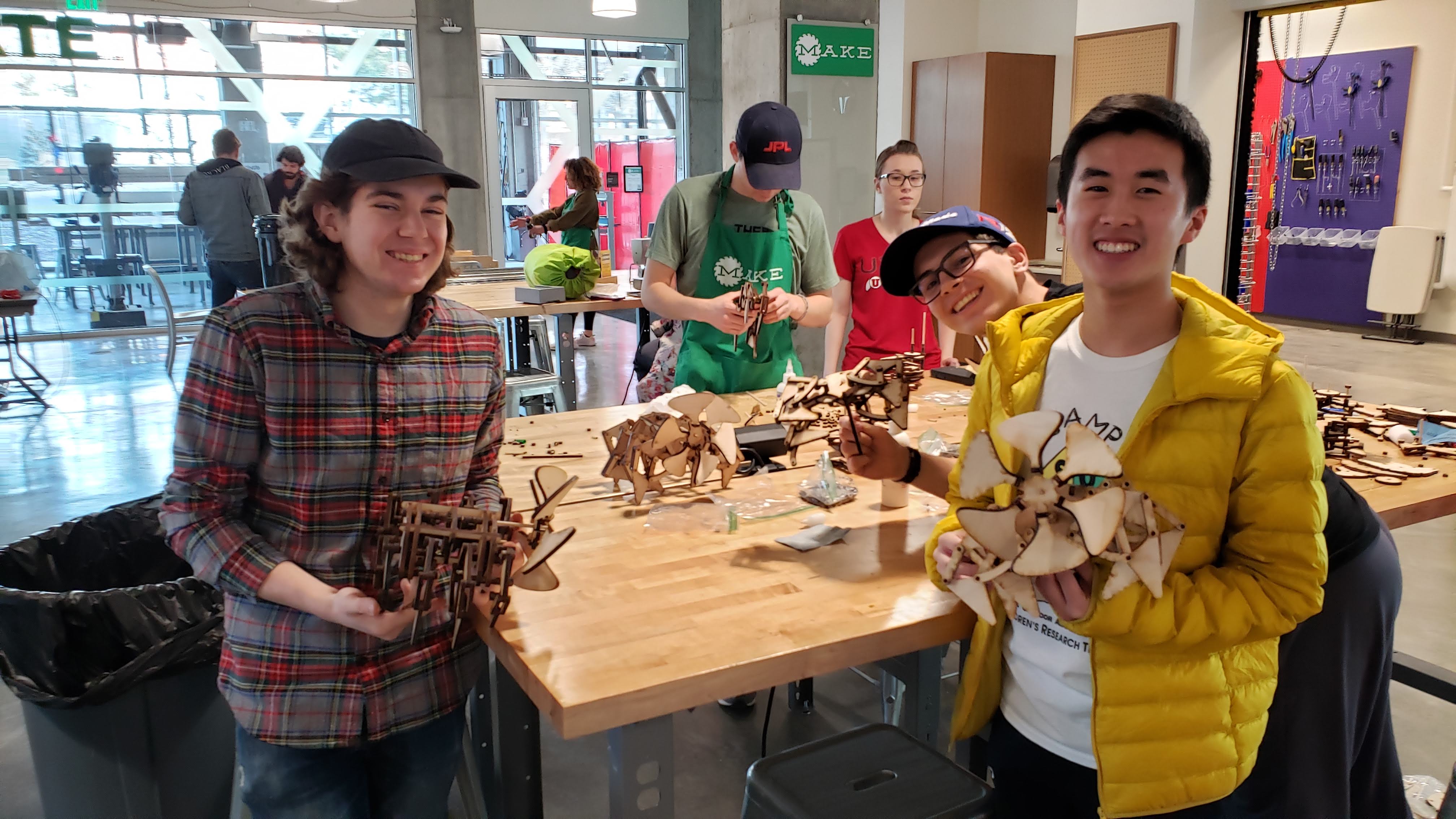
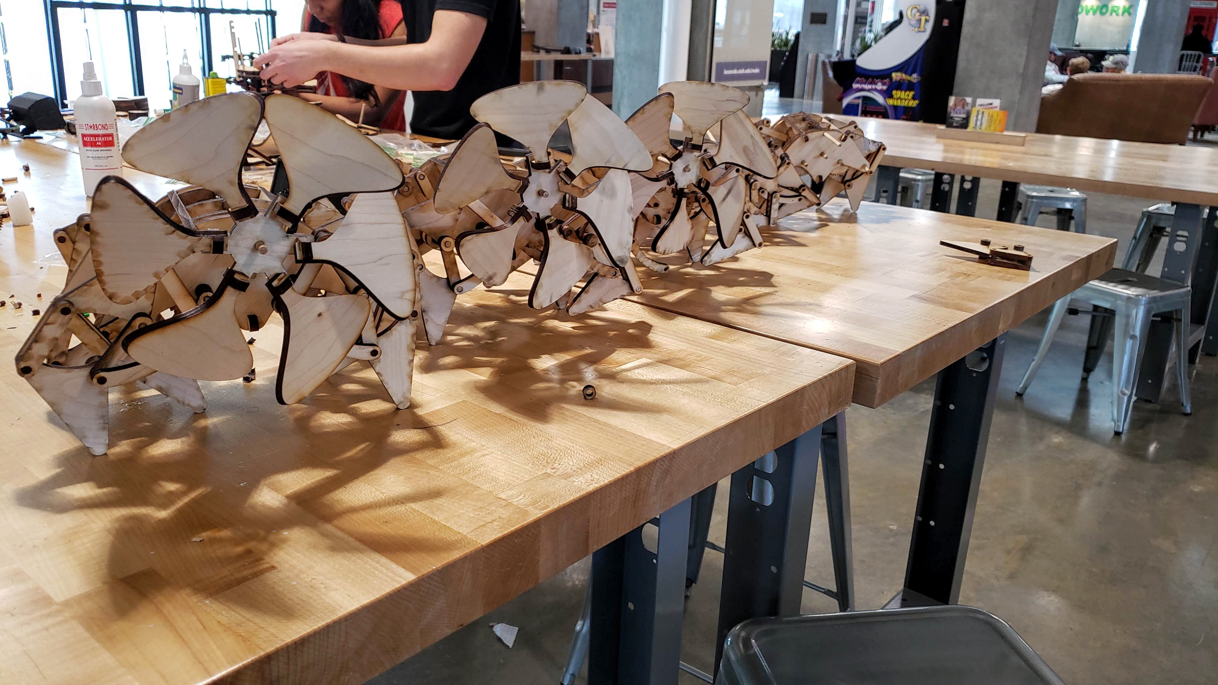
There were some major and minor mishaps, but only one of the six attendees had to abandon their kit (He accidentially poured a large amount of super glue down one of the main axles, locking the legs in place and making it impossible to disassemble.) The other five students had functional machines, and two of them even ran smoother than the example I made myself!
From start to finish the project took about 60 hours. 10 creating the initial Solidworks model, 40 to iterate on the design, 5 to manufacture the final kits, and 5 to setup, teach, and cleanup the workshop itself.
Of course the end products weren’t perfect. I could have continued iterating on them to fine-tune the motion. It would also have been interesting to design another version with a different leg linkage. I considered creating an illustrated instruction manual so that I would be able to sell the kits, or at least give them as gifts without requiring me to guide the asembly. However in the end I decided to be finished. I had made them for the workshop, and with that being a success, I put my functioning model on display in my apartment and shelved those ideas for another time.